
Intermediate transfer unit and image forming apparatus

a transfer unit and image technology, applied in the field of intermediate transfer units and image forming apparatuses, can solve problems such as image defects

Inactive Publication Date: 2019-06-11
CANON KK
View PDF14 Cites 1 Cited by
  • Summary
  • Abstract
  • Description
  • Claims
  • Application Information

AI Technical Summary

Benefits of technology

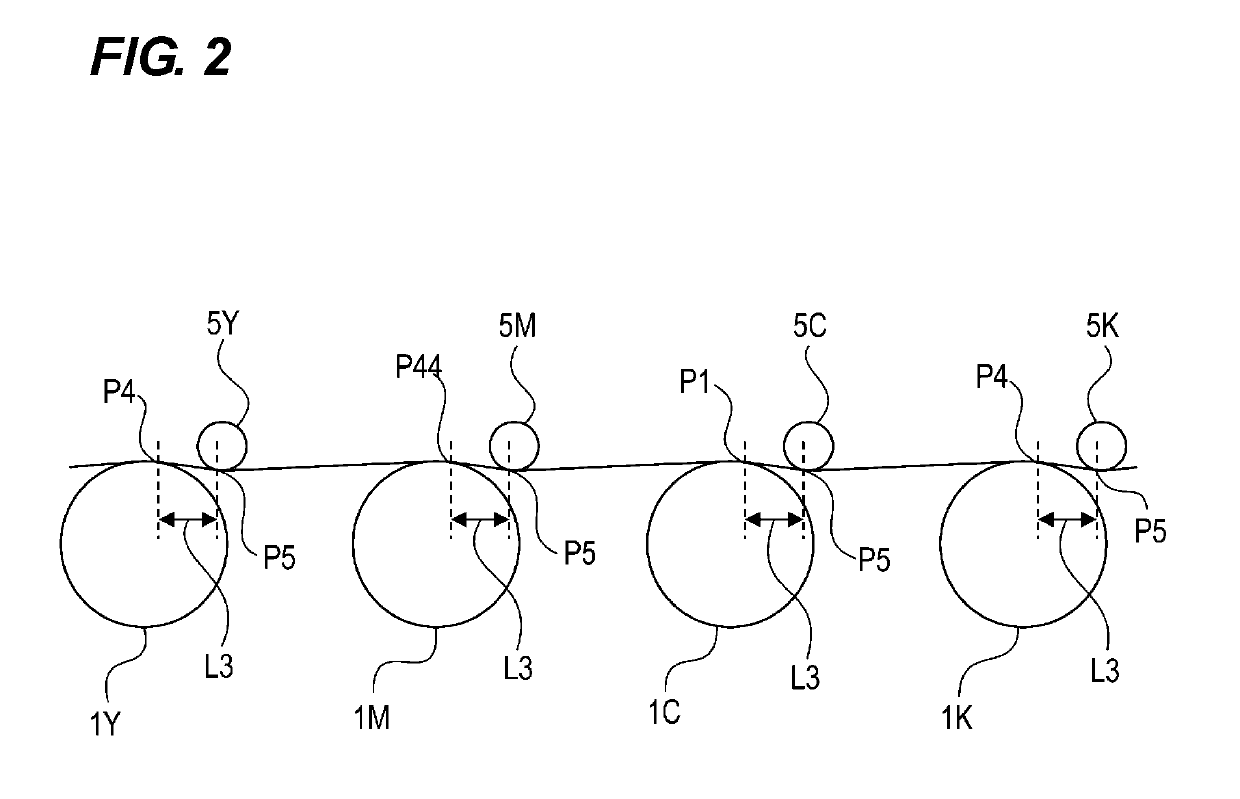
The present invention aims to provide an intermediate transfer unit that can prevent the flow of current from a transfer member to a photosensitive member in a configuration where multiple transfer members can be separated from an intermediate transfer belt.

Problems solved by technology

This may cause image defects.

Method used


Image

  • Intermediate transfer unit and image forming apparatus
  • Intermediate transfer unit and image forming apparatus
  • Intermediate transfer unit and image forming apparatus

Examples


first embodiment

[0020]

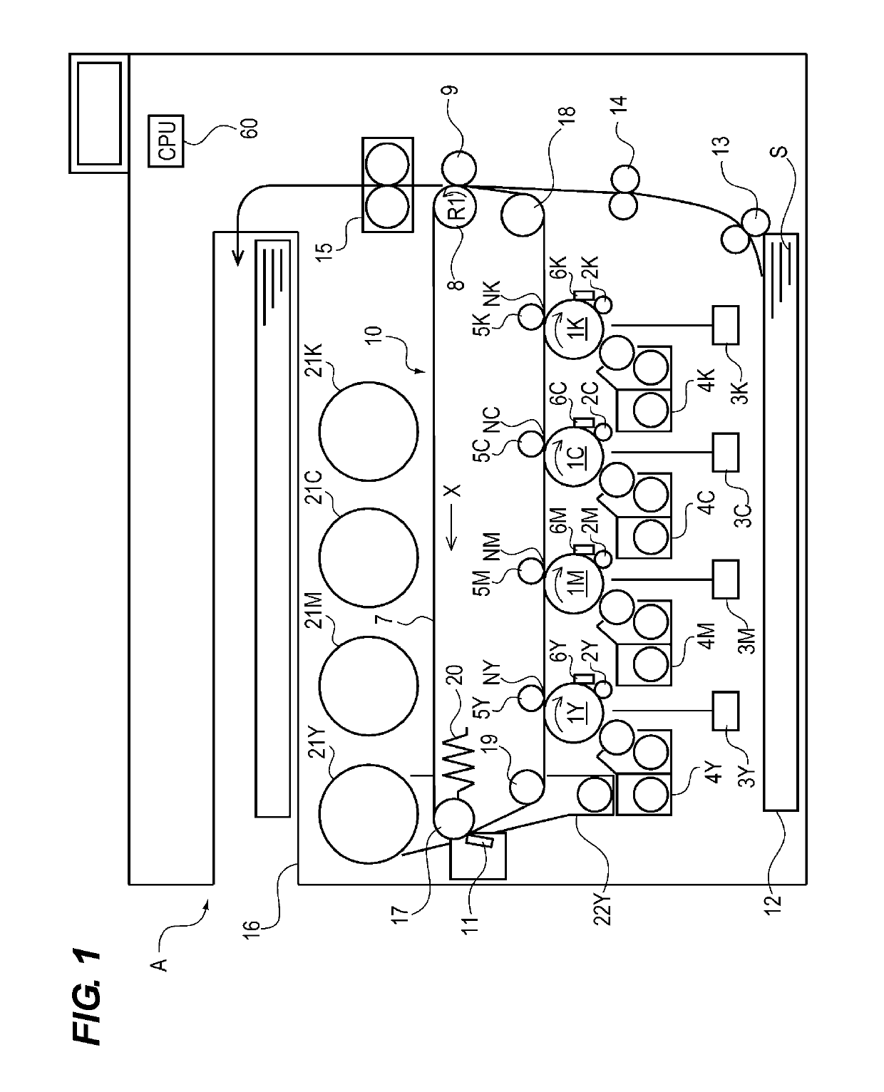
[0021]First, an overall configuration of an image forming apparatus A including an intermediate transfer unit according to a first embodiment of the present invention will be described with reference to the drawings together with an operation at the time of image formation.

[0022]The image forming apparatus A is an electrophotographic type or intermediate transfer tandem type color image forming apparatus which primarily transfers toners of four colors, that is, yellow Y, magenta M, cyan C, and black K, to an intermediate transfer belt, and then secondarily transfers the same onto an image forming medium to form an image.

[0023]As illustrated in FIG. 1, the image forming apparatus A includes an image forming portion which transfers a toner image onto a sheet, a sheet feeding portion which feeds the sheet to the image forming portion, and a fixing portion which fixes the toner image onto the sheet.

[0024]As illustrated in FIG. 1, the image forming portion includes a plurality of p...


PUM


Abstract

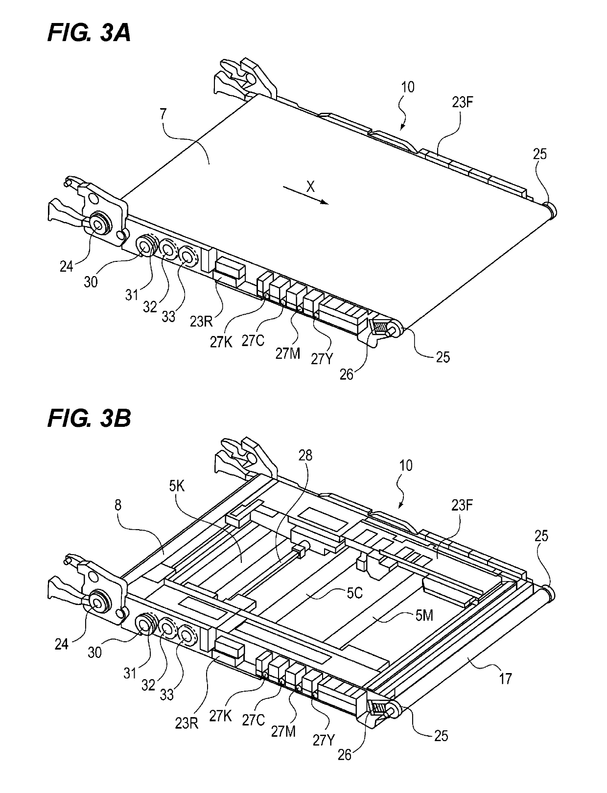
An intermediate transfer unit, which is supported by an image forming apparatus, includes a moving mechanism which is capable of moving to an abutting position at which a first transfer member abuts against an intermediate transfer belt and a separating position at which the first transfer member is separated from the intermediate transfer belt; and a changing mechanism which changes a biasing force for abutting a second transfer member against the intermediate transfer belt. The biasing force is changed such that the biasing force when the first transfer member is at the separating position becomes weaker than the biasing force when the first transfer member is at the abutting position.

Description

CROSS-REFERENCE TO RELATED APPLICATIONS[0001]This application is a Continuation of International Patent Application No. PCT / JP2017 / 011113, filed Mar. 21, 2017, which claims the benefit of Japanese Patent Application No. 2016-080717, filed Apr. 14, 2016, both of which are hereby incorporated by reference herein in their entirety.FIELD OF THE INVENTION[0002]The present invention relates to an intermediate transfer unit included in an image forming apparatus, and an image forming apparatus. Here, the image forming apparatus refers to, for example, an electrophotographic copying machine, an electrophotographic printer (for example, a laser beam printer, an LED printer, or the like), or the like.BACKGROUND ART[0003]Recently, along with an increase in the speed of image forming apparatuses, a configuration in which a plurality of image forming portions having developers of different colors are arranged side by side and the image forming processes of respective colors are processed in para...

Claims


Application Information

Patent Timeline
Patent Type & Authority Patents(United States)
IPC IPC(8): G03G15/00G03G15/16G03G15/01
CPCG03G15/0189G03G15/1615G03G15/0136G03G21/168G03G15/16G03G21/16G03G15/01
Inventor NAKAJIMA, TAKAO
Owner CANON KK
Learn More