Annular excitation power generator structure

A generator and ring-shaped technology, which is applied in the field of ring-shaped excitation generator structure, can solve the problems of ineffective power sources, limited experience in solar and wind power operation, and limited contribution of hydropower generation.

Inactive Publication Date: 2020-08-21
FLY SKY INNOTECH INC
View PDF5 Cites 0 Cited by
  • Summary
  • Abstract
  • Description
  • Claims
  • Application Information

AI Technical Summary

Problems solved by technology

Although there are few problems with hydropower generation, generally speaking, the hydropower generation that can be developed has been effectively developed, and the contribution of hydropower generation to the whole is quite limited. If a large number of dams are to be built, on the one hand, it will be restricted by the envi

Method used


Image

  • Annular excitation power generator structure
  • Annular excitation power generator structure
  • Annular excitation power generator structure

Examples


Example Embodiment

[0031] In the following, a preferred embodiment of the present invention will be described in detail with regard to the structure and composition of the present invention, as well as the functions and advantages that can be produced, in conjunction with the accompanying drawings.

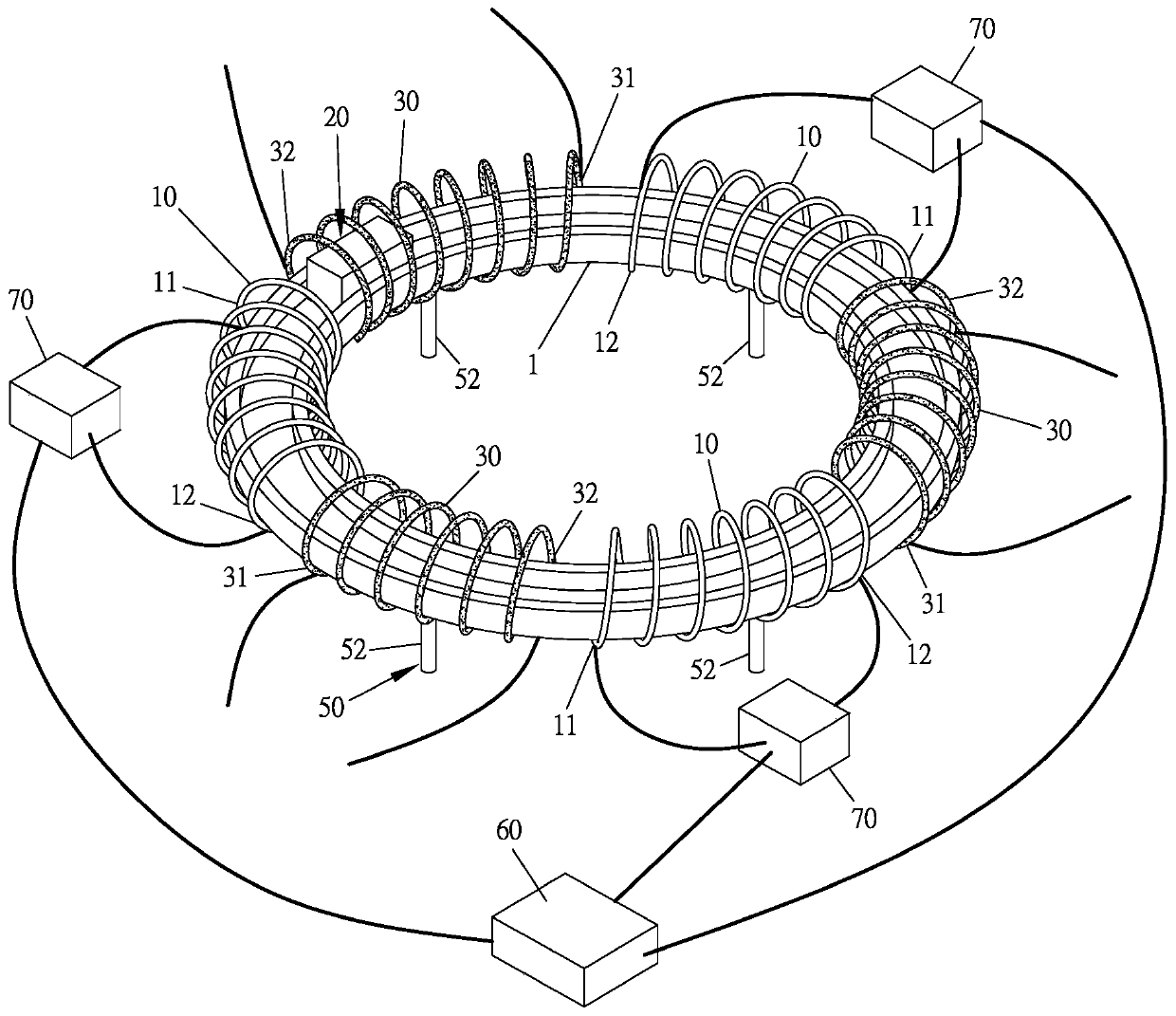
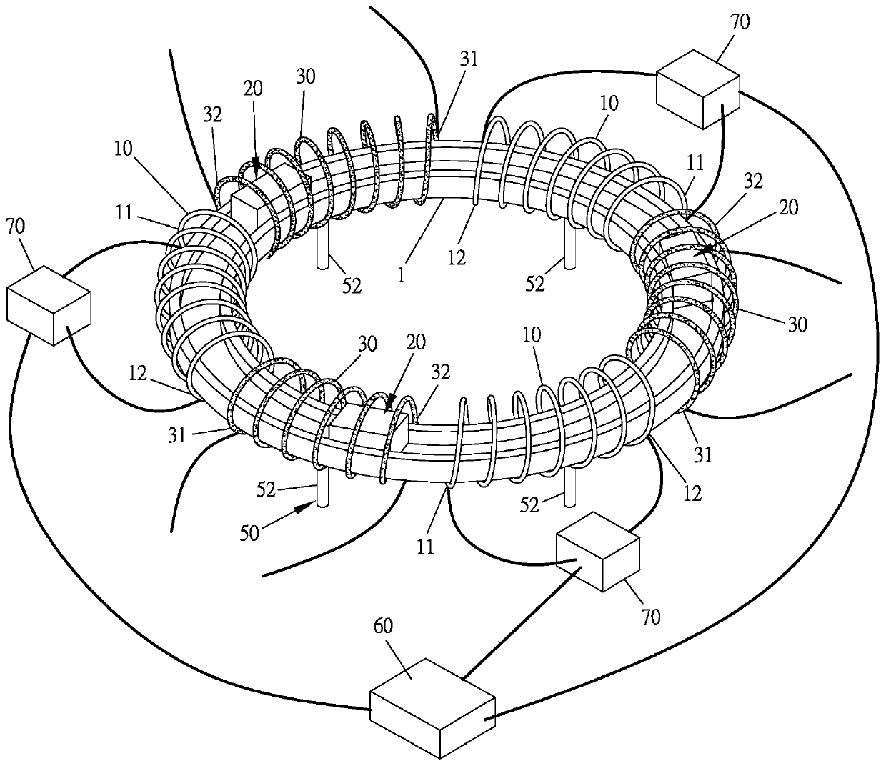
[0032] Please refer to Figure 1 to Figure 3 , which is the ring-shaped excitation generator structure of the present invention, including the following elements:

[0033] A ring track 1 is a ring structure.

[0034] At least one magnetic block 20 is located on the circular track 1 , which can form a closed moving track in the circular track 1 .

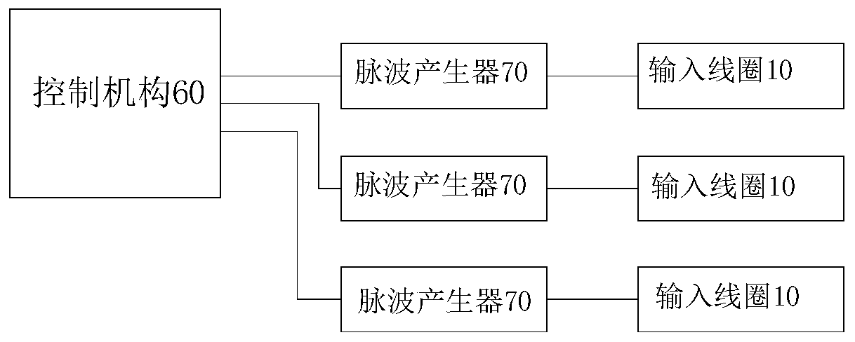
[0035] At least one input coil 10 , each input coil 10 surrounds a part of the circular track 1 , and the circular track 1 runs through the interior of each input coil 10 . Each input coil 10 includes an input terminal 11 and an output terminal 12 .

[0036] At least one pulse wave generator 70 is respectively connected to an input end 11 and an output ...


PUM


Abstract

The invention relates to an annular excitation power generator structure, which comprises: an annular track; at least one magnetic block positioned on the annular track and capable of forming a movingtrack with a closed path in the annular track; at least one input coil, wherein each input coil surrounds a part of the annular track; at least one pulse wave generator connected with a correspondinginput coil; and at least one output coil, wherein each output coil surrounds a part of the annular track and is not in contact with the input coil, and the annular track penetrates through the interiors of the input coils and the output coils. According to the invention, when the pulse wave generator inputs pulse waves to the input coil, the pulse waves generate an excitation effect on the inputcoil, so that a magnetic field is generated in the input coil to drive the magnetic block to move; and when the magnetic block moves on the annular track and passes through the output coil, the outputcoil generates induced current and outputs the induced current outwards, so that the purpose of power generation is achieved.

Description

technical field [0001] The invention relates to a generator structure, in particular to a ring-shaped excitation generator structure. Background technique [0002] With the progress of human civilization, electricity consumption has been increasing. Traditionally, various power generation methods have been developed, such as coal, oil, gas, nuclear energy, solar energy, wind power, hydraulic power and other different forms of power generation. These The traditional power generation method mainly converts various energy sources that exist in nature into electrical energy, and then outputs the electrical energy. Because electric energy can be transmitted effectively and conveniently over long distances, generators become key components in these various power generation methods. [0003] There are already various problems in traditional power generation methods, such as coal, oil, gas, and nuclear energy that pose potential threats to environmental protection, coal, oil, and g...

Claims


Application Information

Patent Timeline
IPC IPC(8): H02K53/00
CPCH02K53/00
Inventor 陈石矶
Owner FLY SKY INNOTECH INC
Why Eureka
Try Eureka