
Technology for capturing, transmitting, and analyzing images of objects

a technology of object images and processing systems, applied in the field of image processing systems and techniques, can solve the problems of inability to quickly and effectively detect, isolate, or quantify damage that may have occurred to an automobile, changes to buildings or other, and no known image processing systems that can quickly and effectively d

Active Publication Date: 2019-06-11
CCC INFORMATION SERVICES
View PDF20 Cites 64 Cited by
  • Summary
  • Abstract
  • Description
  • Claims
  • Application Information

AI Technical Summary

Benefits of technology

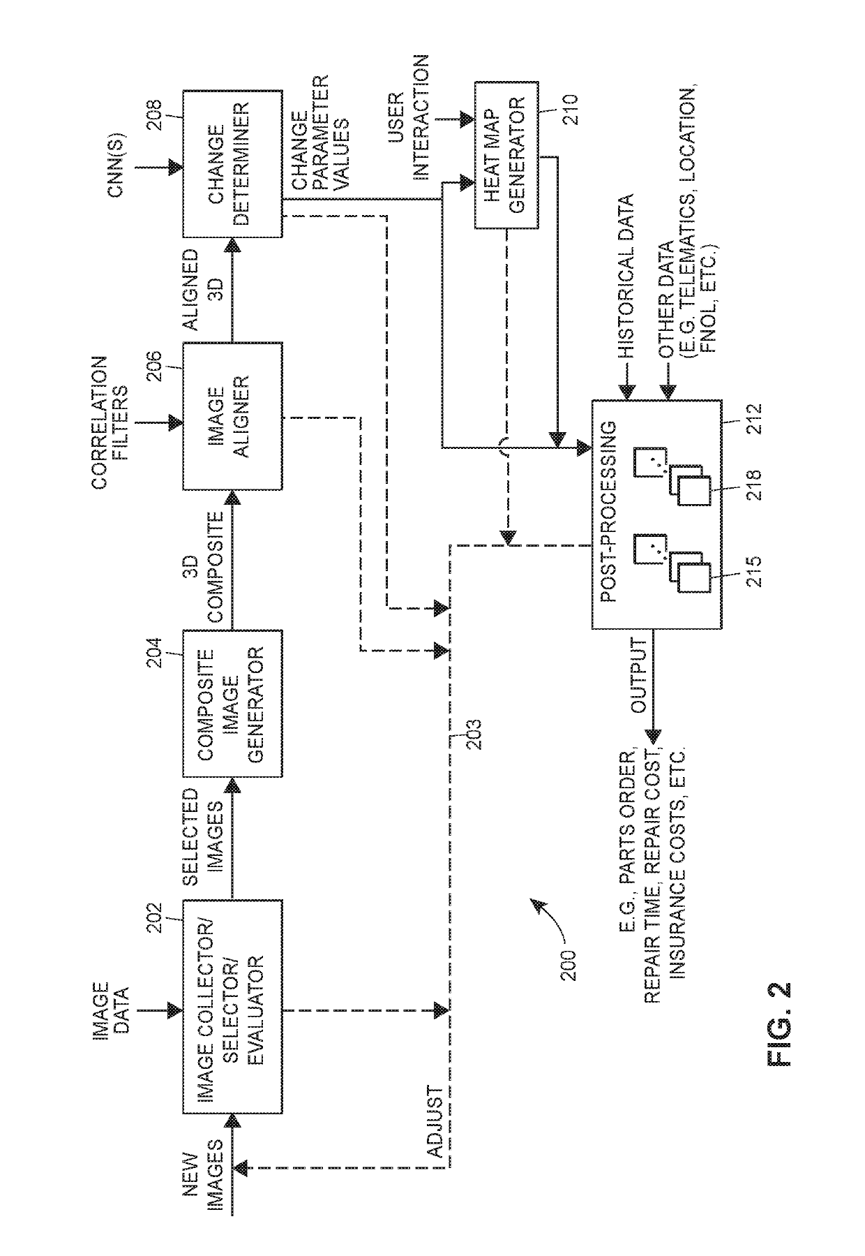
This patent describes a system for analyzing images of vehicles and detecting changes to them. The system includes an user interface device with an image sensor and a device processor. The processor captures images of a target vehicle and sends them to a server. The server stores a database with information about base object models, correlation filters, and convolutional neural networks. The server analyzes the images using these models, filters, and networks to determine what changes have occurred to the vehicle. The server then sends the information about these changes to the user interface device for display to the user.

Problems solved by technology

However, currently, there is no known image processing system that can quickly and effectively detect changes that have occurred to an object as depicted in an image to thereby detect the manner in which an object depicted in the image has changed from a known state or condition.
For example, known image processing systems are unable to quickly and effectively detect, isolate, or quantify damage that may have occurred to an automobile in an accident, changes to buildings or other structure that may have occurred due to further construction on the buildings, due to tornado or flood damage, etc.
While it is possible to compare images of the same object at different times to detect changes to the image of the object, it is difficult to automatically detect or quantify actual changes to the object based on this comparison of the images for a number of reasons.
In particular, such a comparison requires the images of the object to be from the same perspective, angle, distance, etc. which is difficult to achieve in practice.
Moreover, a high fidelity comparison would normally require that the images be obtained from the same camera to account for distortions that would typically be introduced by different cameras taking images at different times. Still further, a simple comparison of images of the same object from the same perspective and using the same camera may still result in the detection of changes that are not substantive in nature due to differences in lighting, surrounding objects, etc.
Moreover, it would be difficult to quantify the nature or type of changes even if such changes could be detected.

Method used


Image

  • Technology for capturing, transmitting, and analyzing images of objects
  • Technology for capturing, transmitting, and analyzing images of objects
  • Technology for capturing, transmitting, and analyzing images of objects

Examples


Embodiment Construction

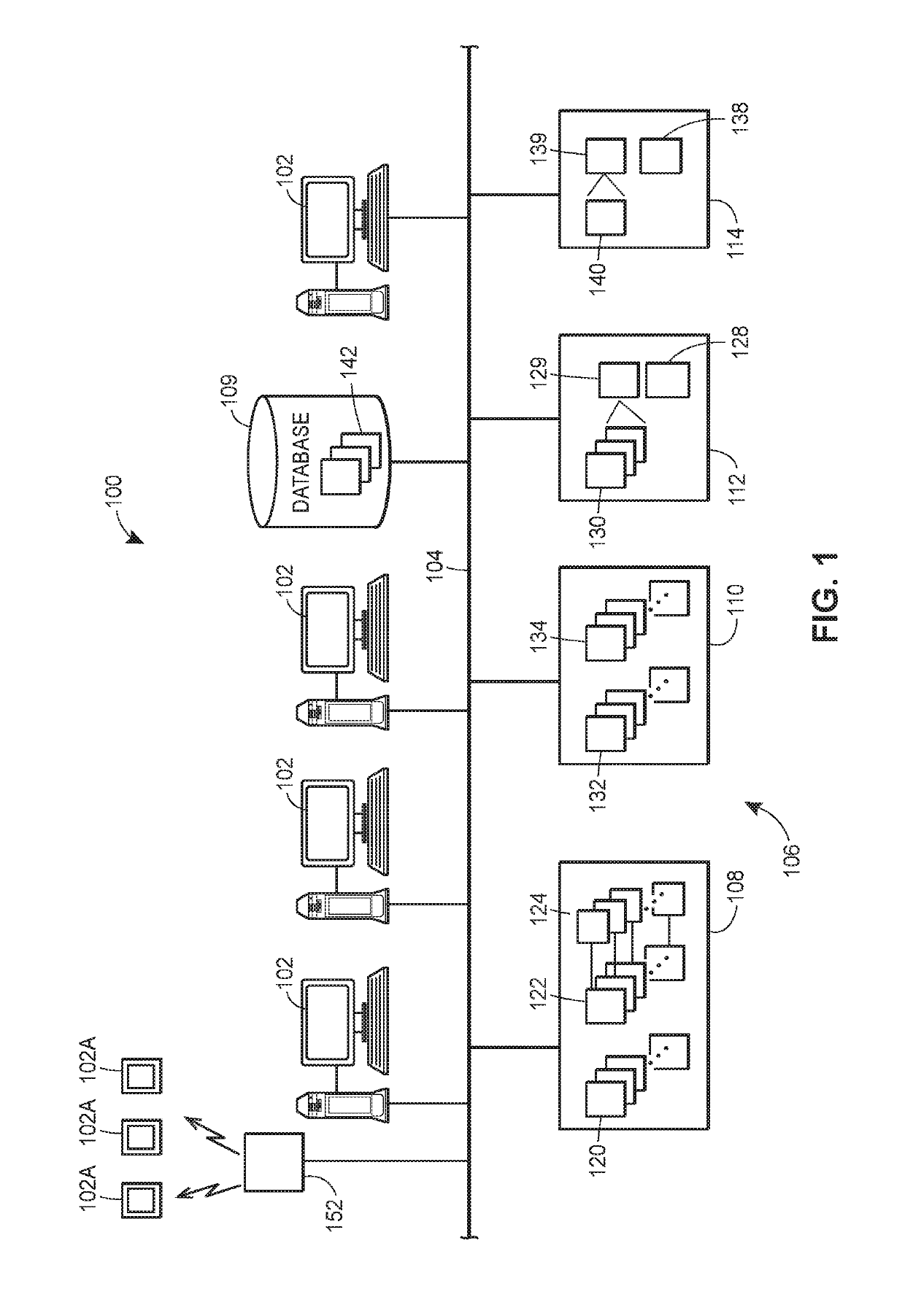
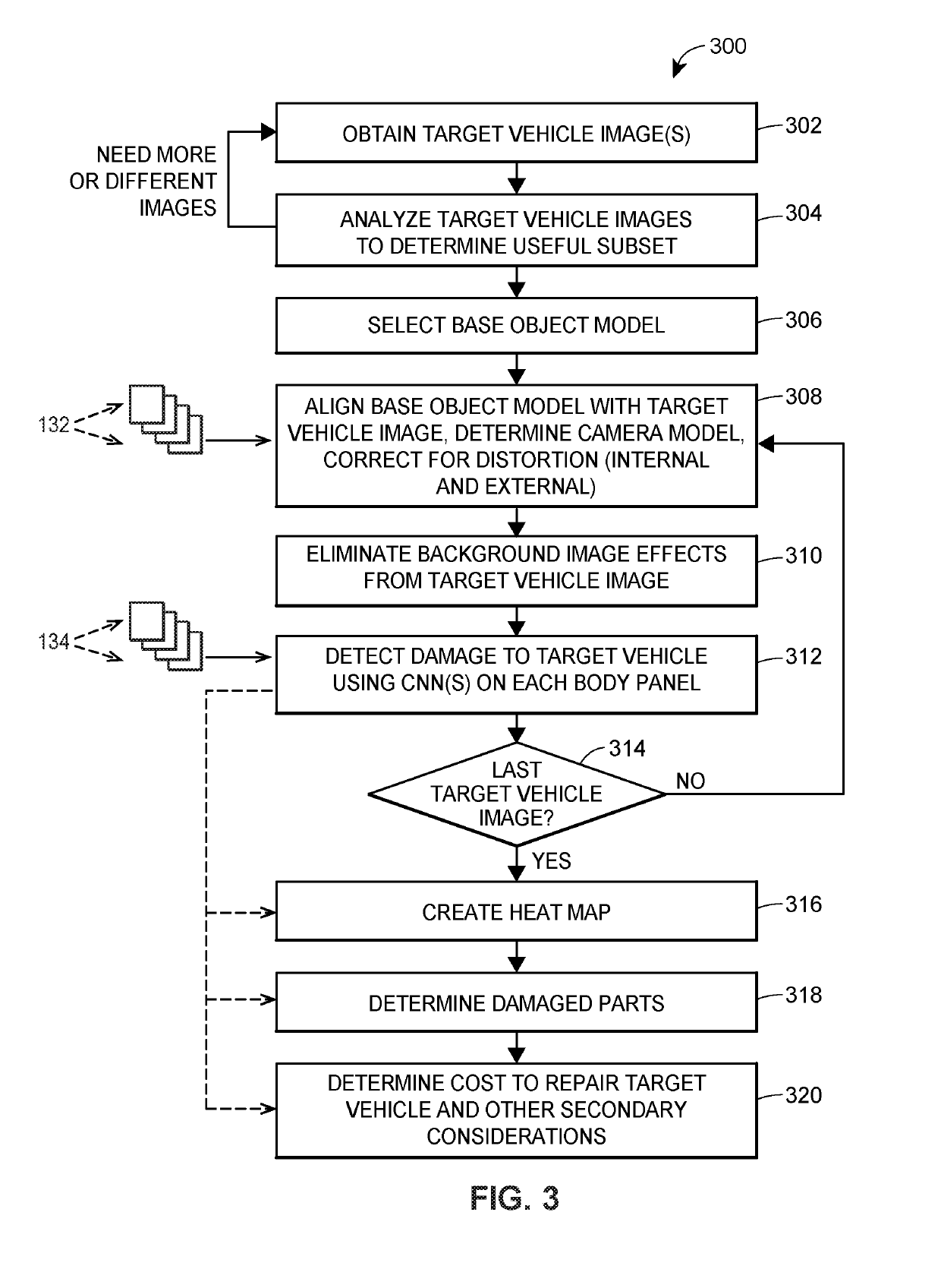
[0025]FIG. 1 illustrates one example of an image processing system 100 which may be used to determine changes to a target object, automatically or semi-automatically, generally by determining differences between one or more images of the target object as changed and one or more images generated from a base model of the object representing the object prior to the changes occurring to the object. After changes to the target object have been determined and quantified in some manner, further processing systems, which may be incorporated into the image processing system 100, may be used to determine secondary characteristics or features associated with the target object, such as the amount of change or damage to the target object (assuming that the changes to the object represent damage), costs associated with repairing or replacing the target object, the time it may take to repair the target object, the progress the target object has undergone in changing states, etc.

[0026]As illustrate...


PUM


Abstract

A system for analyzing images of objects such as vehicles. According to certain aspects, the system includes a user interface device configured to capture a set of images depicting a target vehicle, and transfer the set of images to a server that stores a set of base image models. The server analyzes the set of images using a base image model corresponding to the target vehicle, a set of correlational filters, and a set of convolutional neural networks (CNNs) to determine a set of changes to the target vehicle as depicted in the set of images. The server further transmits, to the user interface device, information indicative of the set of changes for a user to view or otherwise access.

Description

TECHNICAL FIELD[0001]This patent relates to an image processing system and technique, and more particularly, to an image processing system and methodology that detects changes to objects caused by, for example, degradation or damage to the object caused by external or internal forces.DESCRIPTION OF THE RELATED ART[0002]Image processing systems typically operate on images, such as photos, digital images, etc., to enhance the image in some manner or to detect certain features or characteristics of an image, such as to determine information about objects in the image, to recognize persons or things in the image, etc. For example, there are many image processing system that perform character or facial recognition in images to identify text, people, particular buildings, or other features of objects within images in order to automatically identify people, objects, or other features depicted within the image. In many cases, these image processing systems use statistical processing techniq...

Claims


Application Information

Patent Timeline
Patent Type & Authority Patents(United States)
IPC IPC(8): G06N3/08G06T7/00G06F3/0484G06F16/583
CPCG06T7/0046G06T7/0026G06F3/0484G06N3/08G06F16/5838G06T2200/24G06T2207/10004G06T2207/20076G06T2207/20081G06T2207/20024G06N20/10G06N7/01G06N3/045G06Q50/00G06T7/75G06T7/32
Inventor CHEN, KEHALLER, JOHN L.GEORGHIADES, ATHINODOROS S.KANADE, TAKEO
Owner CCC INFORMATION SERVICES
Learn More