Supercharge Your Innovation With Domain-Expert AI Agents!

Optical signal transmitter and optical signal encoder using constant modulus formats, and method for generating modulation codes

Active Publication Date: 2019-06-11
MITSUBISHI ELECTRIC CORP
View PDF11 Cites 8 Cited by
  • Summary
  • Abstract
  • Description
  • Claims
  • Application Information

AI Technical Summary

Benefits of technology

The patent text describes an optical encoder and a method for generating optical data from a symbol using a processor and memory. The optical encoder includes a processor that performs a symbol mapping program and an encoding program. The method involves providing a first constellation format with first and second amplitude rings and circular grids corresponding to predetermined phase angles, applying the first part of the symbol to one of the first or second constellation formats to represent it by one of the amplitude rings with one of the circular grids, applying the second part of the symbol to the other constellation format to represent it by the other amplitude ring with the other circular grids, and providing pairs of superchannels arranged according to time slots, wherein each superchannel includes a number of subcarriers allocated to subchannel numbers. The technical effects of this patent include improved optical data transmission and increased efficiency of the optical encoder.

Problems solved by technology

Fiber nonlinearity is usually the limiting factor in determining the transmission distance of optical communications.
On the other hand, conventional single carrier transmitter cannot offer this option.

Method used


Image

  • Optical signal transmitter and optical signal encoder using constant modulus formats, and method for generating modulation codes
  • Optical signal transmitter and optical signal encoder using constant modulus formats, and method for generating modulation codes
  • Optical signal transmitter and optical signal encoder using constant modulus formats, and method for generating modulation codes

Examples


Embodiment Construction

[0026]Various embodiments of the present invention are described hereafter with reference to the figures. It would be noted that the figures are not drawn to scale elements of similar structures or functions are represented by like reference numerals throughout the figures. It should be also noted that the figures are only intended to facilitate the description of specific embodiments of the invention. They are not intended as an exhaustive description of the invention or as a limitation on the scope of the invention. In addition, an aspect described in conjunction with a particular embodiment of the invention is not necessarily limited to that embodiment and can be practiced in any other embodiments of the invention.

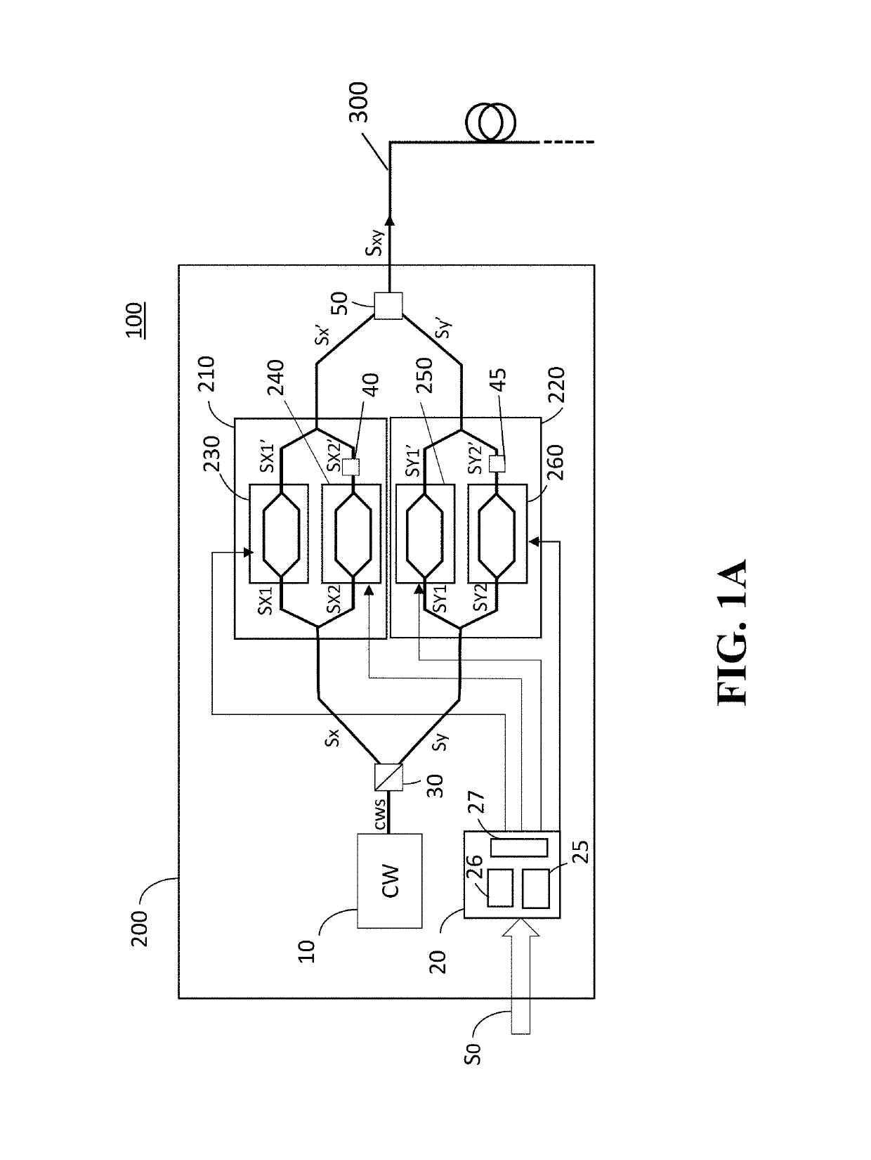
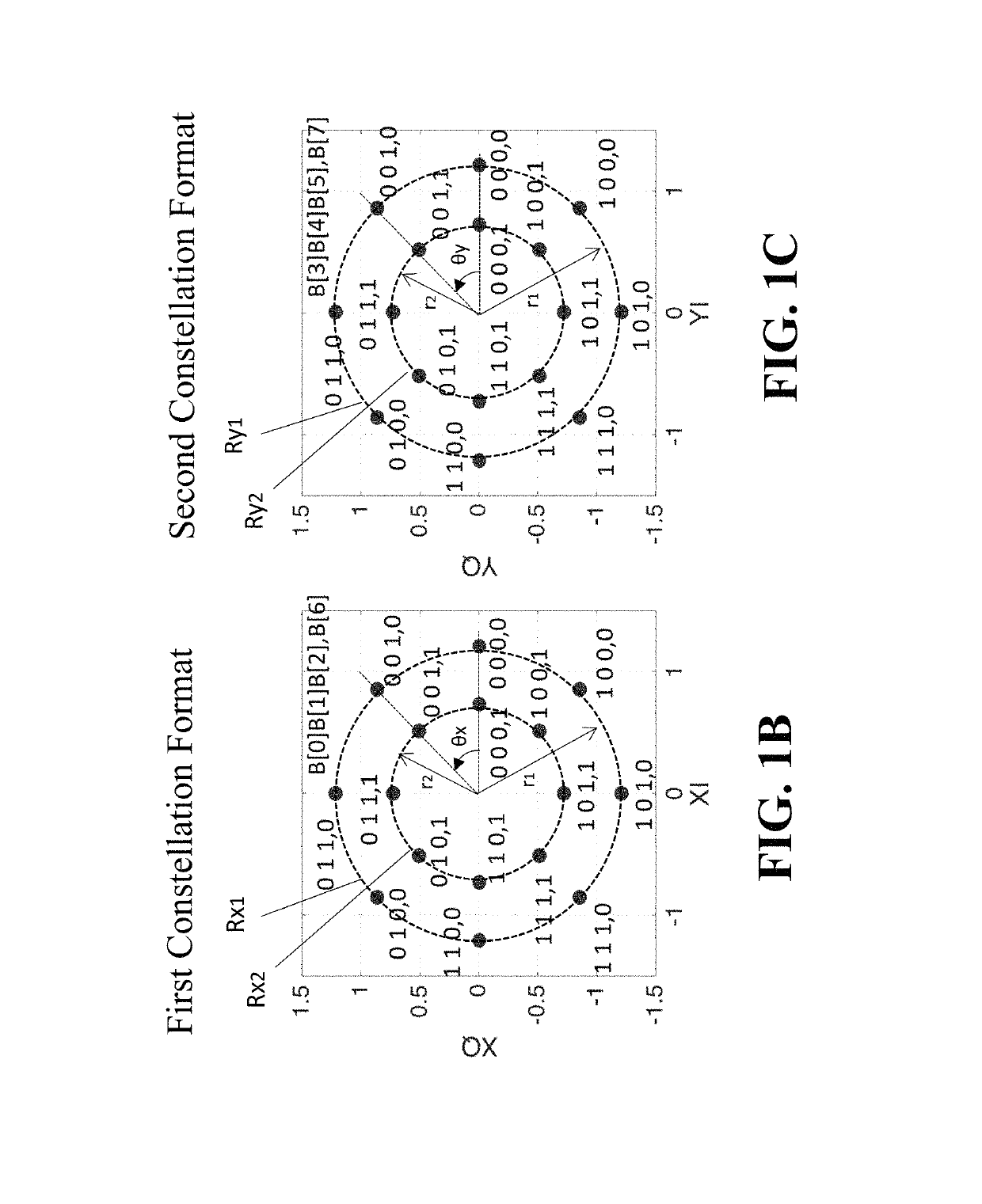
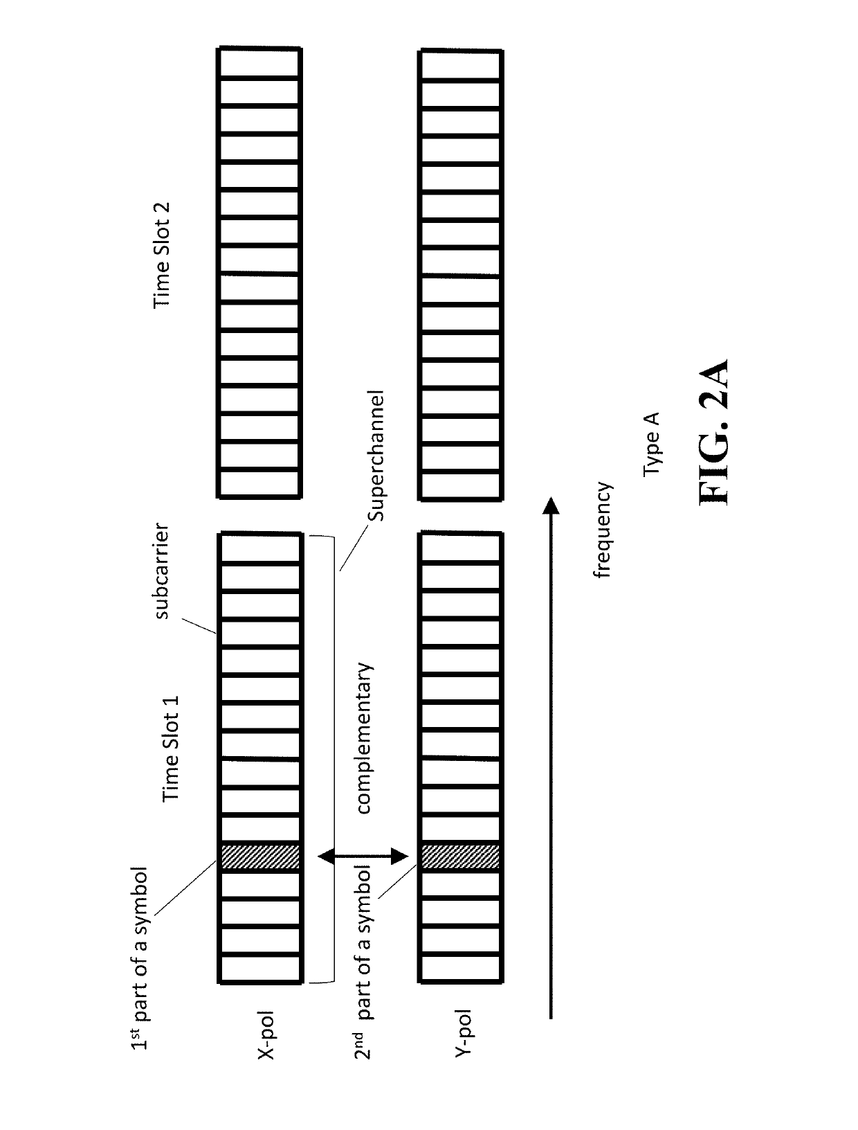
[0027]For removing fiber non linearity in optical communication systems, multi-subcarrier modulation (MSC) can be used. The MSC comprises of 2-4 GB subcarriers for mitigating effects of fiber non linearity. Also, a modulation technique such as Four-dimensional (4D) cons...


PUM


Abstract

An encoder for generating an optical data code from a symbol performs a symbol mapping and an encoding, wherein the symbol mapping performs providing a first constellation format having first and second amplitude rings with circular grids corresponding to phase angles, providing a second constellation format having the first and second amplitude rings with the circular grids corresponding to the phase angles, applying a first part of the symbol to one of the first and second constellation formats to represent the first part of the symbol by one of the first and second amplitude rings with one of the circular grids, and applying a second part of the symbol to another one of the first and second constellation formats to represent the second part of the symbol by one of the first and second amplitude rings with one of the circular grids. The first and the second constellation can be mapped to subcarrier modulation in three different ways.

Description

FIELD OF THE INVENTION[0001]This invention relates to an optical signal transmitter and optical signal encoder, and method for generating modulation codes, and more specifically, an optical signal transmitter and optical communication system for coherent optical communication using constant modulus formats, and method for arranging subcarriers using these constant modulus formats.BACKGROUND OF THE INVENTION[0002]Fiber nonlinearity is usually the limiting factor in determining the transmission distance of optical communications. One of the ways to mitigate fiber nonlinearity is to use multi-subcarrier (MSC) modulation. It has been theoretically and experimentally demonstrated that MSC modulation comprising of 2-4 GB subcarriers is the best in terms of nonlinearity tolerance. This is due to the fact that coherence among subcarriers decreases with narrower subcarriers.[0003]Four-dimensional (4D) constant modulus modulation formats have also been shown to have nonlinearity tolerance com...

Claims


Application Information

Patent Timeline
IPC IPC(8): H04B10/508H04B10/516
CPCH04B10/516H04B10/5161H04B10/541H04B10/5561H04B10/2507H04B10/5053H04B10/532H04L27/2096H04L27/36
Inventor KOJIMA, KEISUKEYOSHIDA, TSUYOSHIKOIKE AKINO, TOSHIAKIMILLAR, DAVIDPARSONS, KIERAN
Owner MITSUBISHI ELECTRIC CORP
Features
  • R&D
  • Intellectual Property
  • Life Sciences
  • Materials
  • Tech Scout
  • Unparalleled Data Quality
  • Higher Quality Content
  • 60% Fewer Hallucinations
Learn More