Counter flow mixer for process chamber

a technology of process chamber and mixer, which is applied in the direction of transportation and packaging, energy-based chemical/physical/physico-chemical processes, coatings, etc., can solve the problems of inability to properly mix the flow of introduced gases, inability to achieve 20:1 length to diameter ratio, and uneven distribution of nh/sub>3/sub>on the wafer being processed

Active Publication Date: 2019-06-18
ASM IP HLDG BV
View PDF2835 Cites 276 Cited by
  • Summary
  • Abstract
  • Description
  • Claims
  • Application Information

AI Technical Summary

Problems solved by technology

In the example process, NH3 cannot be mixed with the Ar / NF3 prior to the PS because disassociation of the NH3 is undesirable.
However, injection into the side of conductance tube that has a low length to diameter ratio (˜2:1 to 12:1) will not provide effective mixing and thus, will lead to an uneven distribution of the NH3 on the wafer being processed.
Issues arising in the example process are attributable in part to: (1) insufficient diffusion time to ensure complete mixing; and (2) preservation of streamlines at required pressures.
However, given the fact that the diameter must be large to preserve the formed F radicals, a 20:1 length to diameter ratio may not be feasible.
At particular pressures, if streamlines of a flowing gas remain undisturbed, a flow of introduced gases may not be able to be properly mixed.

Method used


Image

  • Counter flow mixer for process chamber
  • Counter flow mixer for process chamber
  • Counter flow mixer for process chamber

Examples


Embodiment Construction

[0021]Although certain embodiments and examples are disclosed below, it will be understood by those in the art that the invention extends beyond the specifically disclosed embodiments and / or uses of the invention and obvious modifications and equivalents thereof. Thus, it is intended that the scope of the invention disclosed should not be limited by the particular disclosed embodiments described below.

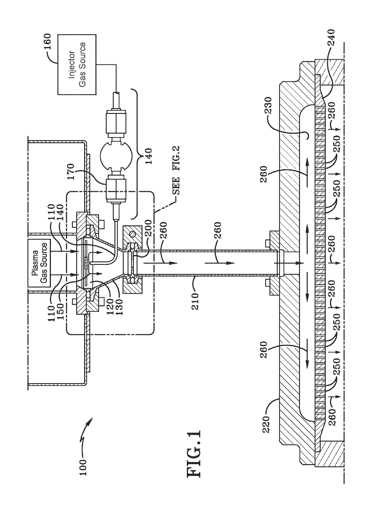
[0022]FIG. 1 illustrates a cross-sectional view of a reaction system 100 in accordance with at least one embodiment of the invention. The reaction system 100 comprises a plasma source. The plasma source (“PS”, illustrated as “Plasma Gas Source” in FIG. 1) generates a first gas 110 from a gaseous mixture using RF energy to excite gas. For example, the plasma source may receive a mixture of Argon and NF3, WF6, or other fluorine containing gas. The plasma source may partially ionize the gaseous mixture to form a glow discharge plasma and in the process form F radicals that are highly chem...


PUM

PropertyMeasurementUnit
lengthaaaaaaaaaa
diameteraaaaaaaaaa
pressuresaaaaaaaaaa

Abstract

A counterflow mixing device for a process chamber is disclosed, comprising an injection tube that introduces a fluid in a manner counter to a flow of a post-plasma gas mixture traveling downward from a plasma source. The invention allows for proper mixing of the fluid as well as avoiding recombination of generated ions and radicals.

Description

CROSS-REFERENCE TO RELATED APPLICATION[0001]This application claims the benefit of U.S. Provisional Application No. 62 / 253,016, which was filed on Nov. 9, 2015 and is incorporated herein by reference.FIELD OF INVENTION[0002]The present disclosure generally relates to semiconductor processing tools. More particularly, the disclosure relates to a low pressure mixer of gas travelling from a small flow tube into a large flow tube.BACKGROUND OF THE DISCLOSURE[0003]Certain cleaning or other low vacuum processes require the mixing of a gas / vapor between a plasma source (PS) and the wafer processing chamber. For example, a NF3 / NH3 process can be used to remove SiO2 from Si. In this process, Ar is mixed with NF3 prior to being injected into a top PS.[0004]Plasma is produced in the PS, which, in addition to some ionization of the Ar / NF3 mix, produces Fluorine radicals that are highly reactive. A relatively large diameter (˜25 mm to 50 mm diameter) with a relatively short length (˜100 mm to 30...

Claims


Application Information

Patent Timeline
Patent Type & Authority Patents(United States)
IPC IPC(8): C23C16/455B01F5/06B01F5/04C23C16/50H01J37/32B01F3/02B01F5/02B01F5/00B01F23/10
CPCB01F5/0461B01F3/02B01F5/0268B01F5/0451B01F5/0651H01J37/3244H01J37/32357H01J37/32449B01F2005/0034B01J19/08B01F25/42B01F23/10B01F2025/918B01F25/25B01F25/3131B01F25/4334H01L2924/1422B01F23/19B01F25/40B01F2101/58B01F25/3133
Inventor STUMPF, JOHN F.WUESTER, CHRIS
Owner ASM IP HLDG BV
Why Eureka
Try Eureka