

Variable firework battery
- Summary
- Abstract
- Description
- Claims
- Application Information
AI Technical Summary
Benefits of technology
Problems solved by technology
Method used
Image

Examples
first embodiment
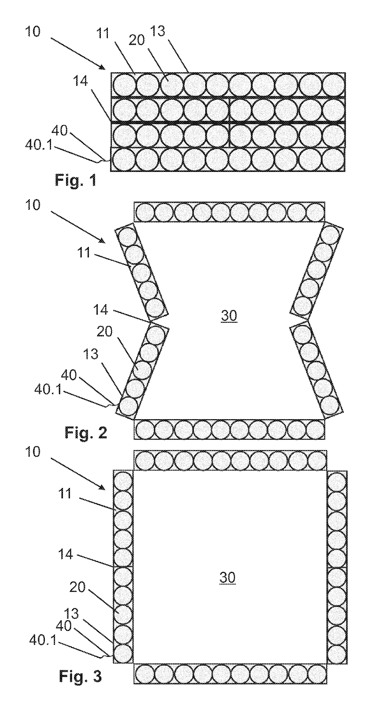
[0042]FIG. 1 schematically shows the firework battery 10 according to the invention in the transport position, comprising six receiving parts 11 here by way of example. Each receiving part 11 is equipped with a plurality of pyrotechnic charges 20, which are arranged in single rows in the receiving parts 11. Each receiving part 11 comprises a border 13 and two hinge parts 14. In the shown transport position, the receiving parts 11 are arranged directly against one another, so that no intermediate space is created between receiving parts 11, whereby the defined support base 30 and the space requirement of the firework battery 10 are as small as possible. The firework battery 10 shown in FIG. 1 has a rectangular shape, wherein the long sides comprise two receiving parts 11 toward the outside, the lengths of which are twice as long as the receiving parts 11 located on the inside. This results in an arrangement of two longer receiving parts 11 on the two long sides, between which four re...
third embodiment
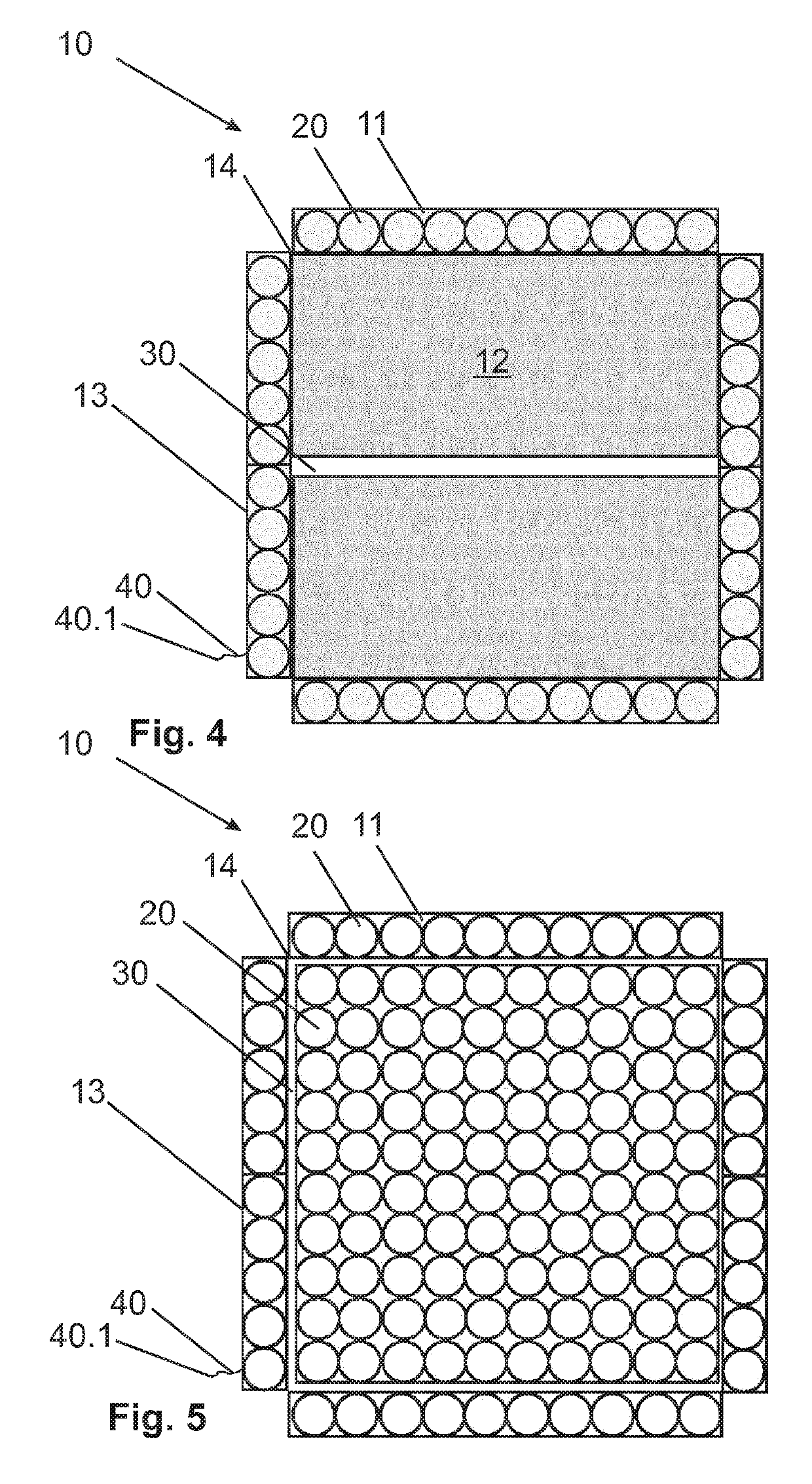
[0047]FIG. 5 shows the firework battery 10 according to the invention, in which a plurality of pyrotechnic charges 20 are arranged in the defined support base 30. In the illustrated usage position, the receiving parts 11 form a square support base 30, which forms sufficient space for further pyrotechnic charges 30. It is conceivable for further pyrotechnic charges 20 to be arranged on a carrier, which, in the usage position of the firework battery 10, is arranged between the receiving parts 11 on the support base 30, so that the number of pyrotechnic charges 20 is considerably increased, whereby the pyrotechnic effects of the firework battery 10 yield a greater variety in the display.
[0048]By arranging the additional pyrotechnic charges 20 on a carrier in the support base 30, an effect comparable to that of the brace elements 12 is achieved. In this way, a displacement of the receiving parts 11 out of the usage position into the transport position is prevented, so that increased saf...
fourth embodiment
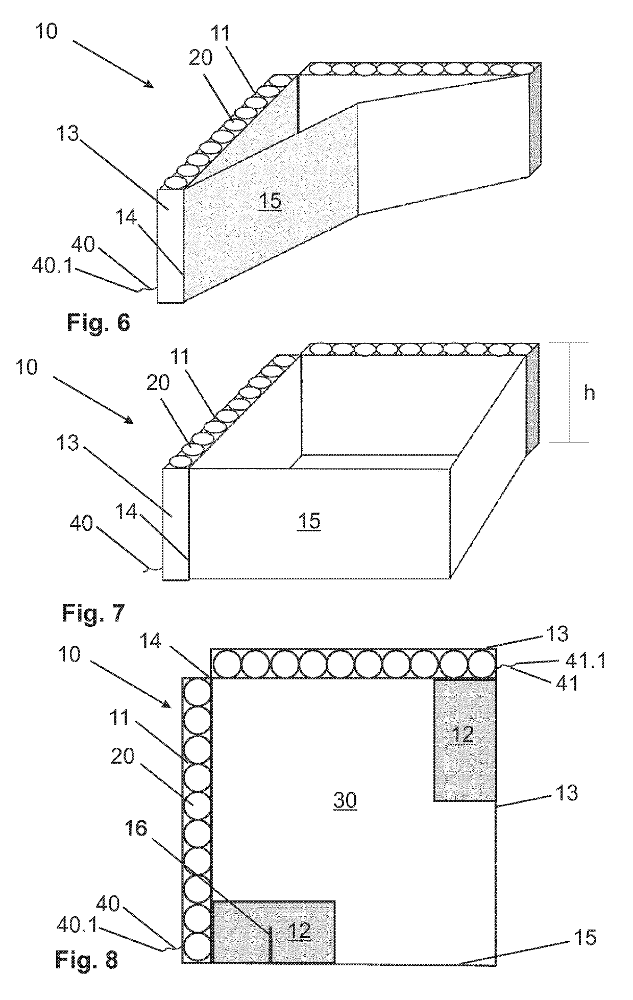
[0051]FIG. 7 shows the firework battery 10 according to the invention in a second usage position, in which the support base 30 defined by the receiving parts 11 and the extension elements 15 is the largest. The extension elements 15 and the receiving parts 11 form square arrangements, in which the stability of the firework battery 10 is accordingly increased compared to the position shown in FIG. 6. According to FIG. 7, a fuse 40 is arranged on the one receiving part 11, wherein the fuse 40 extends along the first receiving part 11 in a manner not shown and is connected to the second receiving part 11 by way of the hinge part 14. A single ignition of the fuse end 40.1 thus allows both the pyrotechnic charges 20 of the first receiving part 11 and the pyrotechnic charges 20 of the second receiving part 11 to be ignited. This results in simple handling due to a single ignition of the fuse 40. Moreover, it is conceivable to route the fuse 40 through the extension elements 15, so that bo...
PUM
 Abstract
Description
Claims
Application Information