Few mode optical fibers for mode division multiplexing having intermediate trenches

a technology of fiber optics and fiber optic fibers, applied in the field of fiber optic transmission, can solve the problems of major limitations on fiber transmission capacity, single-mode fibers suffer from nonlinearity problems, and the optimization of fiber modes becomes more and more difficult, so as to improve the confinement of optical modes, reduce the loss of macrobending, and improve the effect of properties

Active Publication Date: 2019-06-18
DRAKA COMTEQ BV
View PDF16 Cites 2 Cited by
  • Summary
  • Abstract
  • Description
  • Claims
  • Application Information

AI Technical Summary

Benefits of technology

[0033]Such a FMF optical fiber shows a larger core diameter, as compared to prior art FMF fibers, which allows supporting an increased number of LP modes. Moreover, it comprises a depressed trench, which leads to decrease the macrobending losses by improving the confinement of the optical modes within the core. Such a design thus allows to significantly improve the trade-off between DMGD and bend losses.
[0034]Last, such a FMF optical fiber presents a carefully designed interface between the graded-index core and the trench, which allows keeping the DMGDs between any combination of LP guided modes low while keeping the bend loss of any LP guided modes low as well.
[0039]Such a high number of guided modes allows increasing the capacity of an optical system comprising such a few-mode optical fiber, and answers the demand for higher bandwidth in long-haul optical transmission systems.
[0040]A few-mode fiber according to an embodiment of the present disclosure thus guides an increased number of LP modes that can efficiently be used in space-division multiplexed transmissions, as compared to prior art FMFs.
[0075]Such an optical link shows properties similar to those described previously in relation to the FMF optical fiber, notably in terms of number of LP modes supported, and low values of DMGDs. Optical fibers comprised in this optical link show depressed trenches, which allow decreasing the macrobending losses by improving the confinement of the optical modes within the core.

Problems solved by technology

However, single-mode fibers suffer from nonlinearity problems, which are major limitations on fiber transmission capacity.
This optimization, however, becomes more and more difficult when the number of LP modes increases.
Actually, a severe degradation of the bend losses prevents the use of the 9th and 10th mode groups in space-division-multiplexed systems for such fibers.
Undesired modes have respective effective indices that are close to, or less than, the cladding index so as to result in leakage of the undesired modes into the outer cladding.
Although such designs are promising, they do not allow supporting 25 or 30 usable LP modes while reducing the Differential Mode Group Delays as much as desired.
In addition, the profiles disclosed in both documents are not optimized to ensure low bend losses, which, however, are mandatory for FMFs.

Method used


Image

  • Few mode optical fibers for mode division multiplexing having intermediate trenches
  • Few mode optical fibers for mode division multiplexing having intermediate trenches
  • Few mode optical fibers for mode division multiplexing having intermediate trenches

Examples


examples ex.1

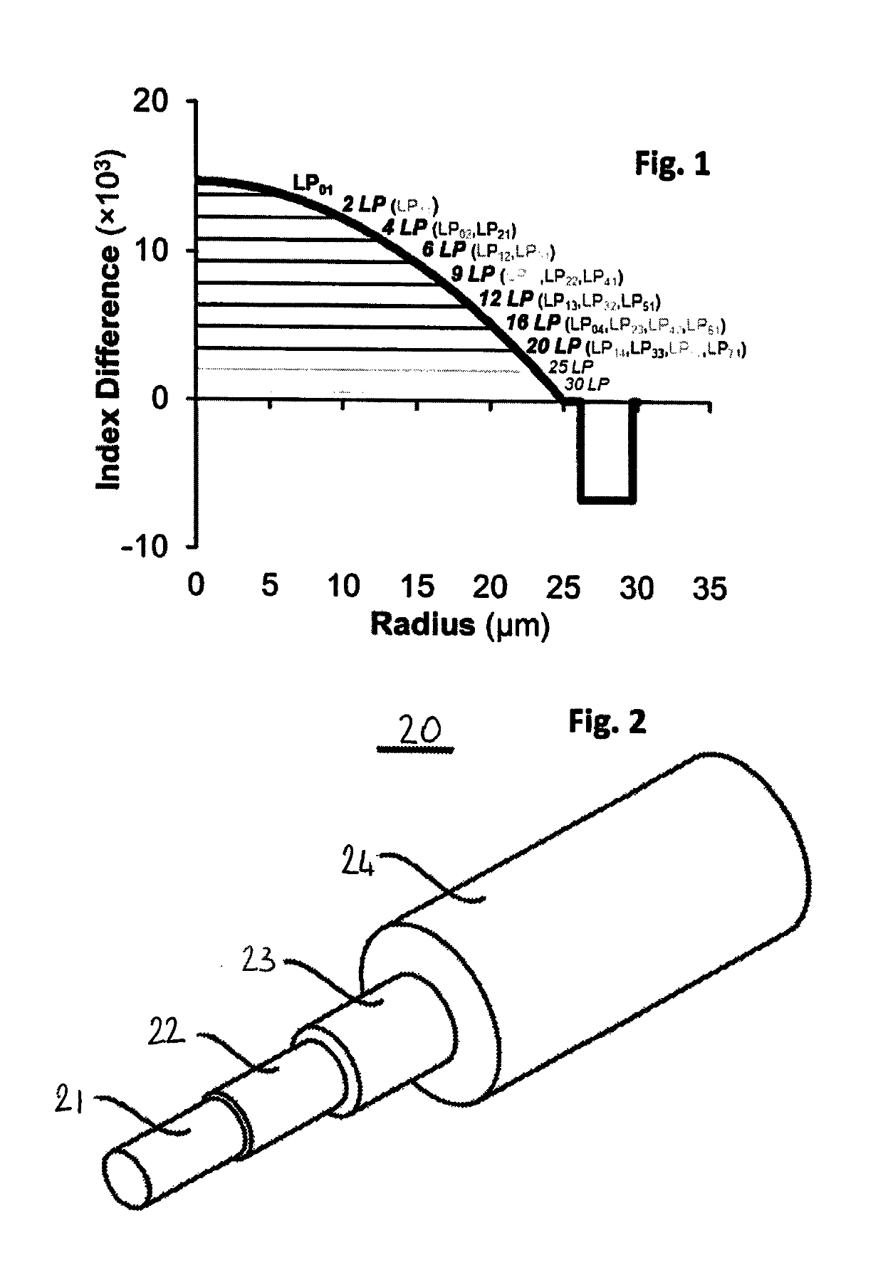
[0140]Examples Ex. 1 to Ex. 4, Ex. 7 and Ex. 10 correspond to FMFs supporting 25 LP guided modes, while examples Ex. 5, Ex. 6, Ex. 8, Ex. 9, Ex. 11 and Ex. 12 correspond to FMFs supporting 30 LP guided modes.

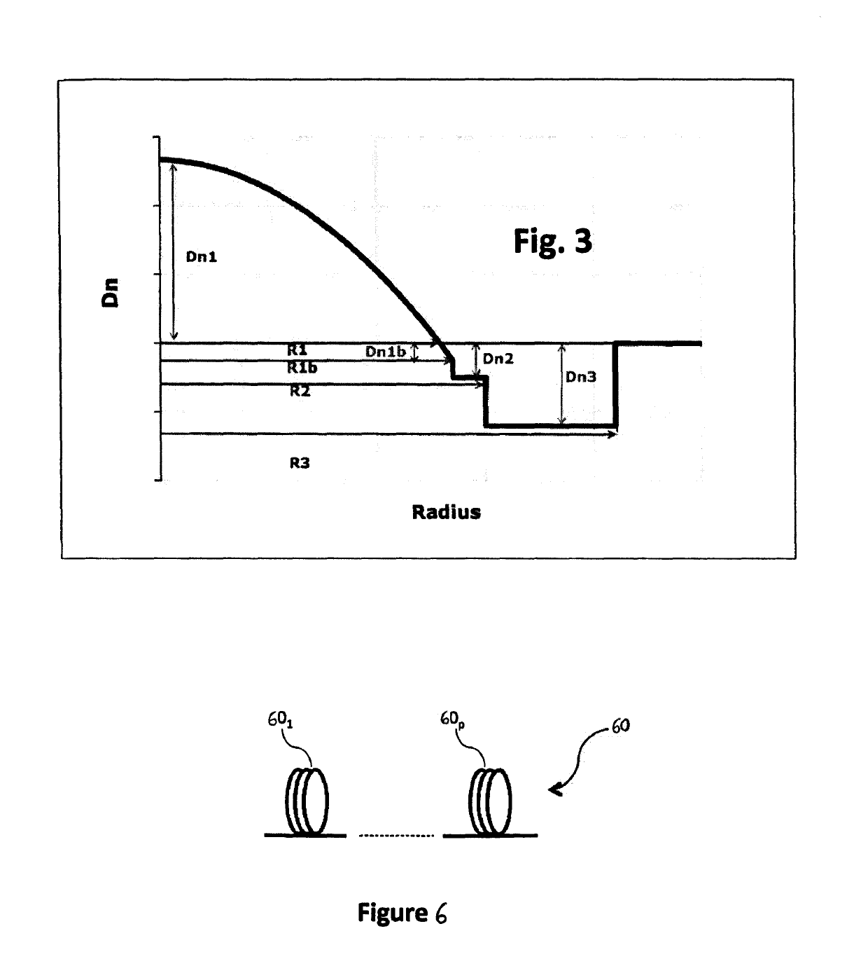
[0141]Examples Ex. 10 to Ex. 12 correspond to a peculiar embodiment where R1=R1b, and the minimal refractive index of the optical core 21 is equal to the refractive index nCl of the outer cladding 24.

[0142]Examples Ex. 7 to Ex. 9 correspond to another peculiar embodiment, where Dn2=Dn1b, i.e. the refractive index of the intermediate trench 22 is equal to the minimal refractive index of the core 21.

[0143]Moreover, examples Ex. 1 to Ex. 6 and Ex. 10 to Ex. 12 correspond to a specific design of the interface between the core and the cladding, which is such that |Dn1b−Dn2|≥0.5×10⁻³, and Min(Dn1b, Dn2)≥−1.5×10⁻³.

examples ex.7

[0144]Examples Ex. 7 to Ex. 9 correspond to another specific design of the interface between the core and the cladding, which is such that |Dn1b−Dn2|−3 and Dn2 is between −5×10⁻³ and −3.5×10⁻³.

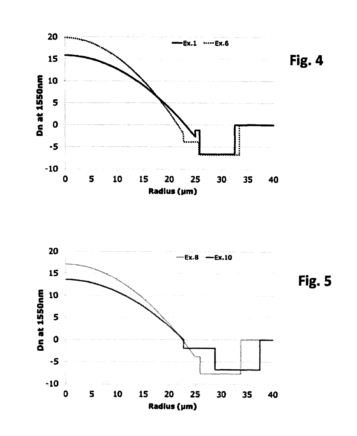
[0145]FIG. 4 graphically provides the refractive index profile of two exemplary FMF optical fibers, corresponding to examples Ex. 1 and Ex. 6 in Table 1. The refractive index difference Dn shown on the y-axis is measured at 1550 nm, and the radius of the FMF fiber shown on the x-axis is expressed in μm.

[0146]The refractive index difference of the FMF of example Ex. 6 is shown in dashed lines. The graded-index core 21 shows a α-profile with α=1.93, a radius R1=21.6 μm at 0 refractive index difference and a maximum refractive index difference Dn1=19.8×10⁻³ at 1550 nm. The α-profile ends at R1b=22.7 μm, with index difference Dn1b=−1.9×10⁻³.

[0147]An intermediate trench 22 is down-doped as compared to the optical core 21 and shows a refractive index difference with the outer cladding 24 Dn2=−3.9×10...

first embodiment

[0191] in FIG. 7A, such an optical system comprises transceivers 71 and receivers 75 optically connected by an optical fiber link 60 that includes at least one span of fiber. Transceivers 71 comprise light sources (such as lasers) and generate n LP modes, referenced 1, 2, . . . , n used in the optical system of FIG. 7A. A mode multiplexer 72 multiplexes the n LP modes and is optically connected to optical link 60, which guides the n multiplexed LP modes, towards a mode demultiplexer 73, which is optically connected to the end of optical link 60.

[0192]Mode demultiplexer 73 demultiplexes the n multiplexed LP modes, and feeds each LP mode into an amplifier 74. At the output of amplifiers 74, LP modes enter receivers 75.

[0193]Such an optical system may comprise M optical links (or M spans of optical fibers). In an example, M=1; in another example, M=2; in another example M=5; in yet another example, M=10. In case the optical system comprises M optical links or spans, it also comprises M...


PUM


Abstract

Few mode optical fibers for mode division multiplexing. The Few Mode Fiber supporting 25 or 30 LP guided modes and includes a graded index core with a α-profile, a radius R1 (at 0 refractive index difference) between 21.5 and 27 μm and a maximum refractive index difference Dn1 between 12.5×10⁻³ and 20×10−3, and an end of the α-profile at a radius R1b, with index difference Dn1b; a trench surrounding the core with radius R3 between 30 and 42 μm and refractive index difference Dn3 between −15.10−3 and −6.10−3, an intermediate depressed trench with a radius R2, with R1b<R2<R3 and a refractive index difference Dn2, with Dn3<Dn2<0, wherein: for |Dn1b−Dn2|>=0.5×10⁻³, Min(Dn1b, Dn2)≤−1.5×10⁻³, and for |Dn1b−Dn2|<0.5×10⁻³, Dn2 is between −5×10⁻³ and −3.5×10⁻³.

Description

1. FIELD OF THE INVENTION[0001]The present disclosure relates to the field of fiber optic transmission, and, more specifically, to improved few-mode fiber designs for mode division multiplexing.2. BACKGROUND[0002]An optical fiber is conventionally constituted of an optical core, which transmits an optical signal, and of an optical cladding, which confines the optical signal within the optical core. To that end the refractive index of the core, n0, is greater than the one of the cladding, nCl. An optical fiber is generally characterized by a refractive index profile that associates the refractive index (n) with the radius (r) of the optical fiber: the distance r with respect to the center of the optical fiber is shown on x-axis and the difference Dn between the refractive index at radius r, n(r), and the refractive index of the optical cladding nCl is shown on y-axis.[0003]Nowadays, two main categories of optical fibers exist: multimode fibers and single-mode fibers. In a multimode f...

Claims


Application Information

Patent Timeline
Patent Type & Authority Patents(United States)
IPC IPC(8): G02B6/028G02B6/036H04J14/04
CPCG02B6/0288G02B6/0365G02B6/03638H04J14/04
Inventor SILLARD, PIERREMOLIN, DENISBIGOT, MARIANNE
Owner DRAKA COMTEQ BV
Why Eureka
Try Eureka