Magnetic-drive axial-flow fluid displacement pump and turbine

a technology of axial flow and fluid displacement, which is applied in the direction of machines/engines, magnetic bearings, mechanical equipment, etc., can solve the problems of large design and unwieldy

Inactive Publication Date: 2019-06-18
WALSH RAYMOND J
View PDF4 Cites 10 Cited by
  • Summary
  • Abstract
  • Description
  • Claims
  • Application Information

AI Technical Summary

Problems solved by technology

This design is large and unwieldy compared to other pump designs, and the shaft must be sealed where it penetrates the pipe.

Method used


Image

  • Magnetic-drive axial-flow fluid displacement pump and turbine
  • Magnetic-drive axial-flow fluid displacement pump and turbine
  • Magnetic-drive axial-flow fluid displacement pump and turbine

Examples


Embodiment Construction

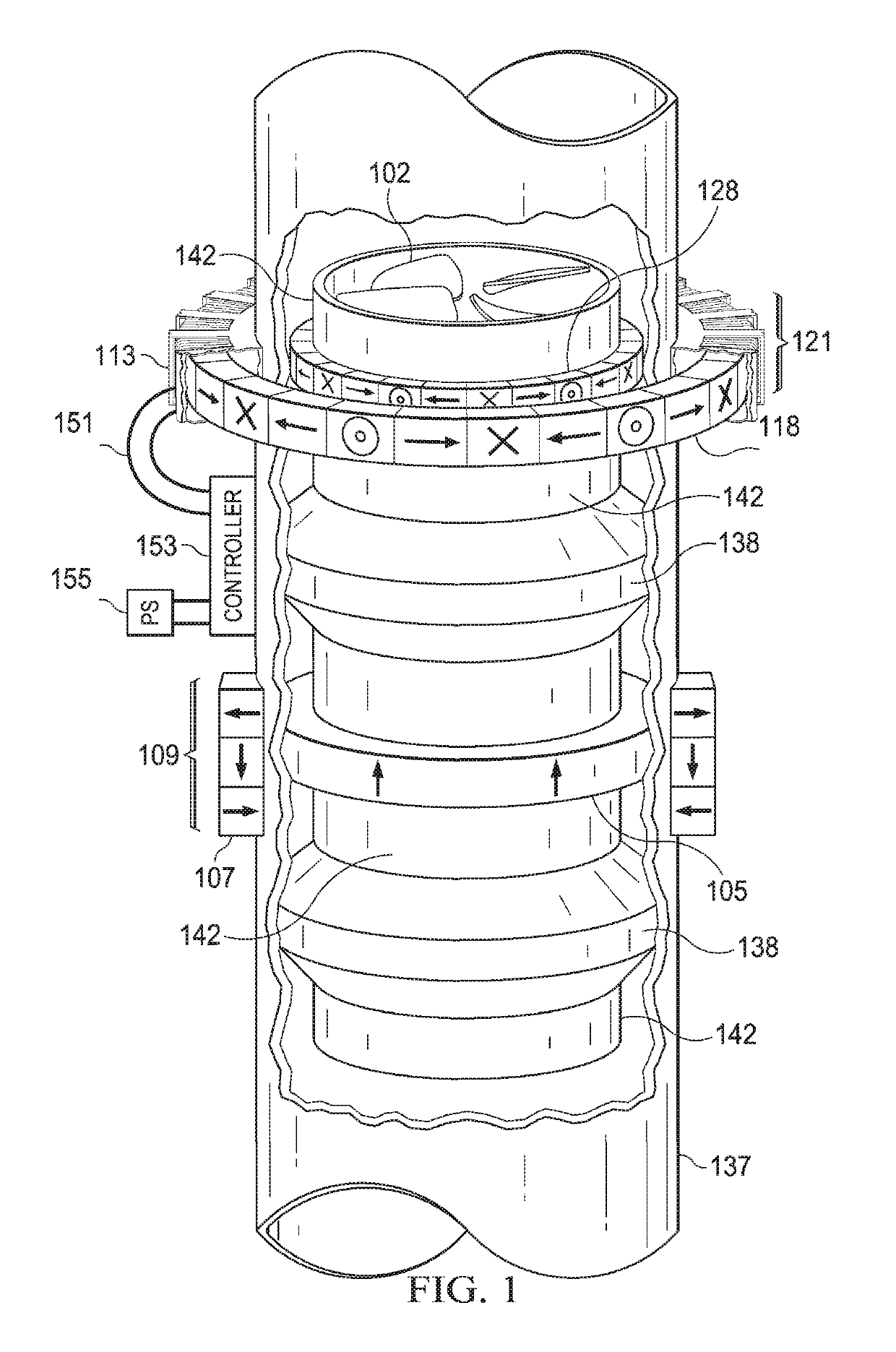
[0016]FIG. 1 is a perspective view of one embodiment a magnetic drive axial-flow pump and turbine.

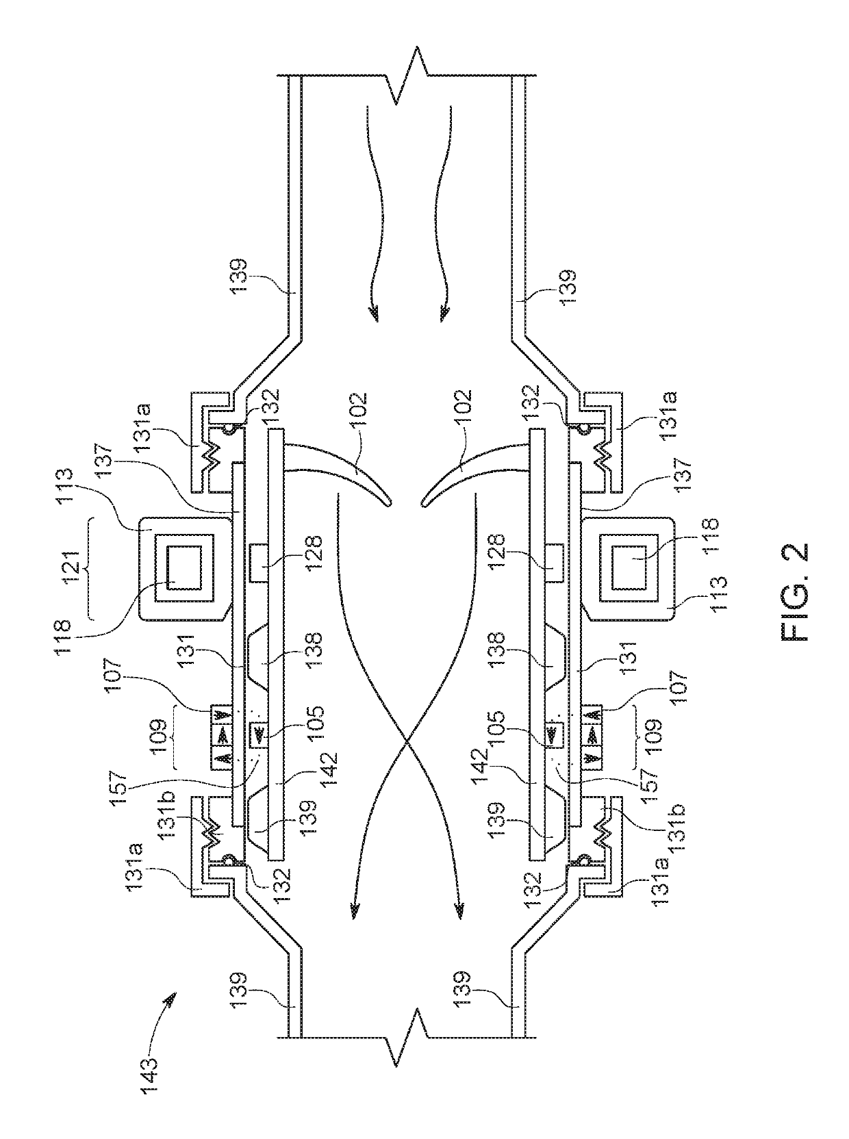
[0017]FIG. 2 is a side view schematic of one embodiment a magnetic drive axial-flow pump and turbine.

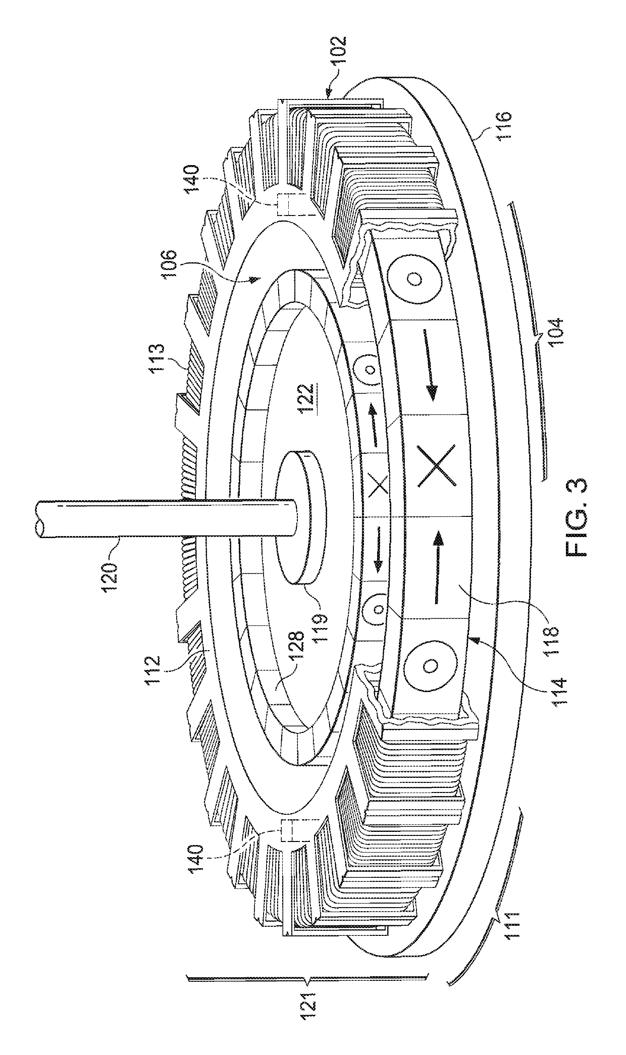
[0018]FIG. 3 is perspective view and cut away of a permanent magnet motor and generator.

[0019]FIG. 4a is a schematic of a rotational sequence of one embodiment of a motor configured for three-phase alternating current, or for rolling biphasic coil control in a first position.

[0020]FIG. 4b is a schematic of a rotational sequence of a motor configured for rolling biphasic coil control in a second position.

[0021]FIG. 4c is a schematic of a rotational sequence of a motor configured for rolling biphasic coil control in a third position.

[0022]FIG. 5 is a schematic representation of an inner secondary rotor coupled to an outer primary rotor with an induction cylinder within the gap between the rotors.

[0023]FIG. 6 is a graphic representation of percent torque transfer versus depth of insertion o...


PUM


Abstract

What is disclosed are embodiments of magnetic torque transfer devices utilizing torque transfer by magnetic induction in which an induction cylinder fabricated from an electrical conductor is interposed into the gap between a pair of magnetically coupled primary and secondary rotors. Rotation of the induction cylinder relative to the coupled rotors evokes magnetic torque transfer in accordance with Lenz's Law. The primary rotor rotates within a toroid shaped stator. The stator may be configured for rolling biphasic coil control. The secondary rotor is attached to a propeller. The device may function as a turbine when fluid is directed to flow over the propeller. The device may function as a pump when AC power is supplied to the stator. Rolling biphasic motor control includes dividing motor coils into increments, then configuring groups of contiguous increments into virtual coils, which revolve in tandem with the primary rotor so to achieve continuous and optimal torque transfer with minimum torque ripple.

Description

PRIORITY / CROSS REFERENCE TO RELATED APPLICATIONS[0001]This application claims priority benefit to U.S. Patent Application No. 62 / 596,376 filed Dec. 8, 2017, and is a continuation-in-part of co-pending U.S. patent application Ser. No. 15 / 878,236 filed Jan. 23, 2018, and is a continuation-in-part of U.S. patent application Ser. No. 14 / 523,687 filed on Oct. 24, 2014, which issues as patent U.S. Pat. No. 10,125,814 on Nov. 13, 2018, the disclosures of which are hereby incorporated by reference in their entireties.TECHNICAL FIELD[0002]The disclosed technology generally relates to pumps and turbines that employ permanent magnet motors and generators having magnetically coupled rotors, means and methods of transferring torque, as well as pumps and turbines that employ passive magnetic bearings.BACKGROUND[0003]U.S. patent application Ser. No. 15 / 878,236 discloses magnetic induction torque transfer, which employs an induction cylinder interposed between rotors for torque transfer by magnetic...

Claims


Application Information

Patent Timeline
Patent Type & Authority Patents(United States)
IPC IPC(8): H02K21/14F04D25/06H02K7/18F01D1/20H02K11/30F16C32/04H02K16/02H02K11/21H02K7/14H02K7/09
CPCH02K16/025F01D1/20F04D25/06F16C32/0408H02K7/09H02K7/14H02K7/1823H02K11/21H02K11/30H02K21/14F01D15/10F02C1/02F05D2240/511F05D2240/515F16C2360/00F16C2360/23H02K11/33
Inventor WALSH, RAYMOND J.
Owner WALSH RAYMOND J
Why Eureka
Try Eureka