Fold flex circuit for LNOP

a technology of flex circuit and optical probe, which is applied in the direction of application, diagnostic recording/measure, printed circuit non-printed electric component association, etc., can solve the problems of many difficulties relating to motion-induced noise, and achieve the effect of optimizing material usage, low cost and maximizing the amount of material used

Active Publication Date: 2019-06-18
MASIMO CORP
View PDF954 Cites 271 Cited by
  • Summary
  • Abstract
  • Description
  • Claims
  • Application Information

AI Technical Summary

Benefits of technology

[0007]The present disclosure describes a low cost sensor and a streamlined assembly method for optimized material usage for the use of flexible printed circuit and other sensor materials. In some embodiments, the configuration of the sensors is intended to maximize the amount of material used so as to keep material cost to a minimum.

Problems solved by technology

Many difficulties relating to motion-induced noise have been encountered in providing such an optical probe inexpensively.

Method used


Image

  • Fold flex circuit for LNOP
  • Fold flex circuit for LNOP
  • Fold flex circuit for LNOP

Examples


Embodiment Construction

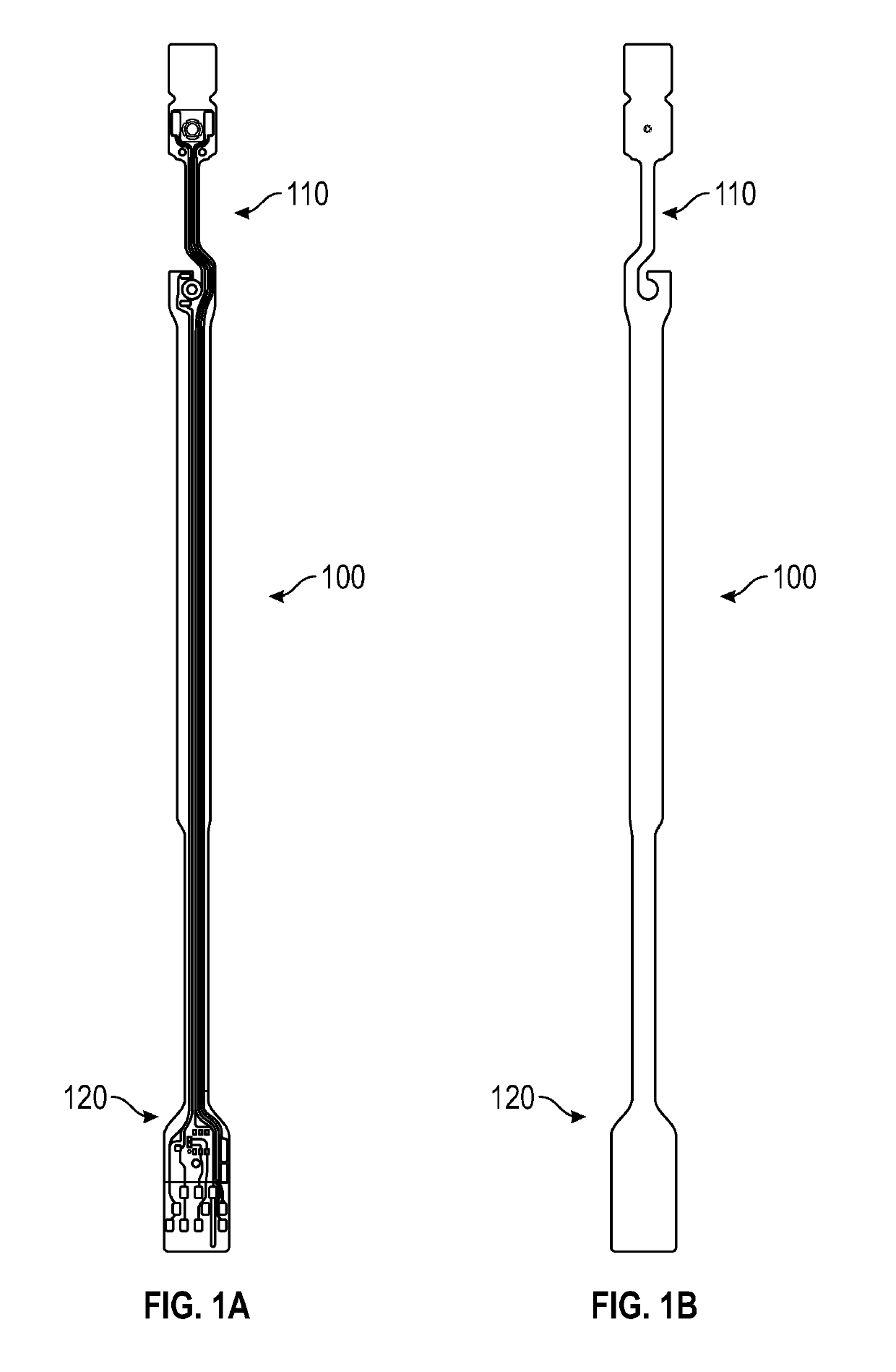
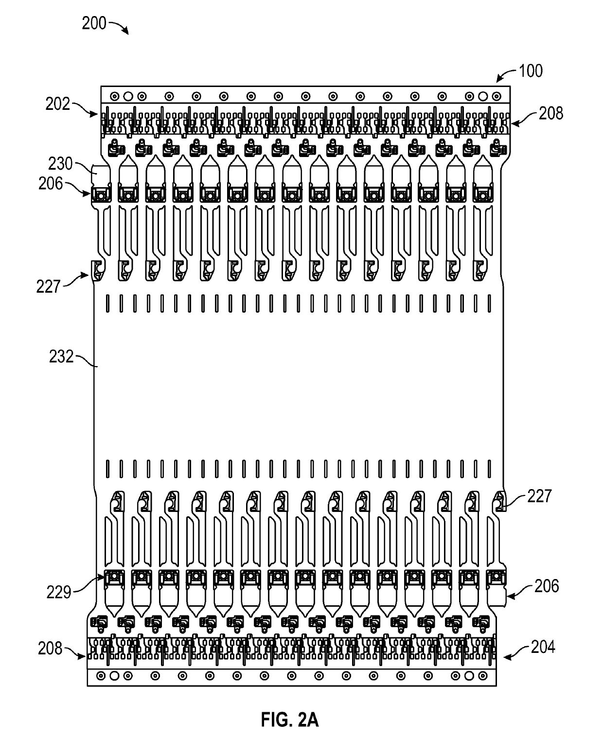
[0029]The present disclosure provides a low cost sensor and methods of assembly and manufacture of the low cost sensor. In some embodiments, the sensor circuits are configured such that each of the flex circuits for each of the plurality of sensors is tessellated or nested with one another as it is manufactured. In some embodiments, this configuration maximizes the number of circuits that can be manufactured and assembled from a set of materials. Such a configuration further minimizes the amount of material wasted.

[0030]The present disclosure also describes a method for assembling an L-shaped sensor or bent sensor from a straight sensor. Previous manufacturing methods for L-shaped sensors created substantial waste as the profile of the L-shaped sensor prevented the flex circuits from being printed in a staggered formation so as to maximize the use of the substrate material. By assembling the L-shaped sensor from a straight sensor, the profile of the flex circuit is minimized and the...


PUM

PropertyMeasurementUnit
angleaaaaaaaaaa
angleaaaaaaaaaa
angleaaaaaaaaaa

Abstract

Various sensors and methods of assembling sensors are described. In some embodiments, the sensor assembly includes a first end, a body portion, and a second end. The first end can include a neck portion and a connector portion and the second end can include a flap, a first component, a neck portion, and a second component. A method is also described for sensor folding. The method can include using a circuit with an attached emitter and a detector that is separated by a portion of the circuit. The method can also include folding the portion of the circuit such that a first fold is created through the emitter and folding the portion of the circuit such that a second fold is created such that the first fold and second fold form an angle.

Description

INCORPORATION BY REFERENCE TO ANY PRIORITY APPLICATIONS[0001]This application claims the priority benefit under 35 U.S.C. § 119(e) of U.S. Provisional Application No. 62 / 112,918, filed Feb. 6, 2015, and U.S. Provisional Application No. 62 / 212,071, filed Aug. 31, 2015, the entire contents of which are hereby incorporated by reference and should be considered a part of this specification. Any and all applications for which a foreign or domestic priority claim is identified in the Application Data Sheet as filed with the present application are hereby incorporated by reference under 37 CFR 1.57.FIELD OF THE DISCLOSURE[0002]The present disclosure relates to low-noise, disposable and reusable optical probes which may be used to sense optical energy passed through a medium to determine the characteristics of the medium.BACKGROUND[0003]Energy is can be transmitted through or reflected from a medium to determine characteristics of the medium. For example, in the medical field, instead of ex...

Claims


Application Information

Patent Timeline
Patent Type & Authority Patents(United States)
IPC IPC(8): A61B5/00H05K3/22A61B5/1455H05K3/00A61B5/024A61B5/026H05K1/18
CPCH05K3/22A61B5/0059A61B5/1455H05K3/0097A61B5/0261A61B2562/0233A61B2562/0238A61B2562/12A61B2562/164A61B2562/166A61B2562/182H05K1/189H05K3/0052H05K2201/0154H05K2201/10151H05K2203/1545
Inventor TRIMAN, BENJAMIN C.SCHMIDT, JOHNABDUL-HAFIZ, YASSIR KAMELAL-ALI, AMMAR
Owner MASIMO CORP
Why Eureka
Try Eureka