Air mattress for gatch bed

a technology of air mattress and gatch bed, which is applied in the field of air mattress for gatch bed, can solve the problems of air cells b>3/b> of high pressure tending to fail down, and achieve the effects of reducing stress, preventing the body from sliding, and early recovery from bedsores

Active Publication Date: 2019-07-02
PARAMOUNT BED CO LTD
View PDF18 Cites 3 Cited by
  • Summary
  • Abstract
  • Description
  • Claims
  • Application Information

AI Technical Summary

Benefits of technology

[0051]According to the present invention, when a back raising operation in the gatch bed is operated, after start of the back raising operation (the back tilt angle has been equal to or greater than a predetermined angle), immediately, the air cells being deflated at that moment is inflated with the maximum pressure of inflating and deflating mode, to thereby make all the air cells inflated. Accordingly, even if an excessive stress from the reactive force from the back of the bed user at the start of the back raising operation is applied on the air cells being in the expanded mode and adjacent to the deflated air cells to compress and bring down the air cells being in the expanded mode, all the air cells come to the inflated mode immediately after start of the back raising operation. Therefore, the above-described shrinkage and fall of the air cells as well as shrinkage of the air mattress with respect to the bed longitudinal direction due to the shrinkage and the fail will not occur. Accordingly, it is also possible to prevent the bed user's body from sliding in the bed longitudinal direction. Further, as a result of reducing stress causing the bed user's body to slide, the risk of generating bedsores can be towered and early recovery from bedsores can be expected.
[0052]Since when back raising is being operated, alternate inflation and deflation of air cells is repeated on a cycle shorter than that at the time of the normal control, it is possible to further reliably prevent the bed user's body from sliding. That is, inflation of all the air cells after start of back raising can make the air mattress unlikely to shrink as a whole. Thanks to the geometrical relation of the bed at the time of back raising the undersurface of the air mattress 2 that is in contact with the bottoms of unvaried dimensions will not change its length in the longitudinal direction of the bed while the top surface of the air mattress 2 becomes shorter in the longitudinal direction of the bed. This will cause stress that slides the bed user on the back bottom to the foot side. To deal with this, the air pressure of air cells on one of the lines is reduced so as to temporarily lower the contact pressure of the body against the air mattress in the corresponding areas. As a result, thanks to the shrinkage of the top surface of the air mattress, the downward stress acting on the bed user from the air mattress is released. Thus, it is possible to prevent sliding of the body.

Problems solved by technology

Further, the air cells 3 of high pressure tend to fail down due to the bed user's weight if the pressure of the adjacent air cells is low.

Method used


Image

  • Air mattress for gatch bed
  • Air mattress for gatch bed
  • Air mattress for gatch bed

Examples


Embodiment Construction

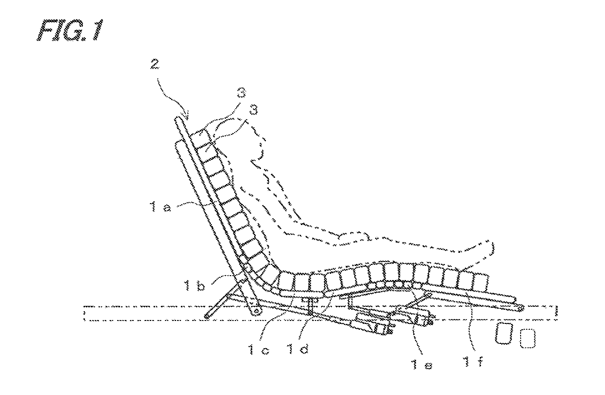
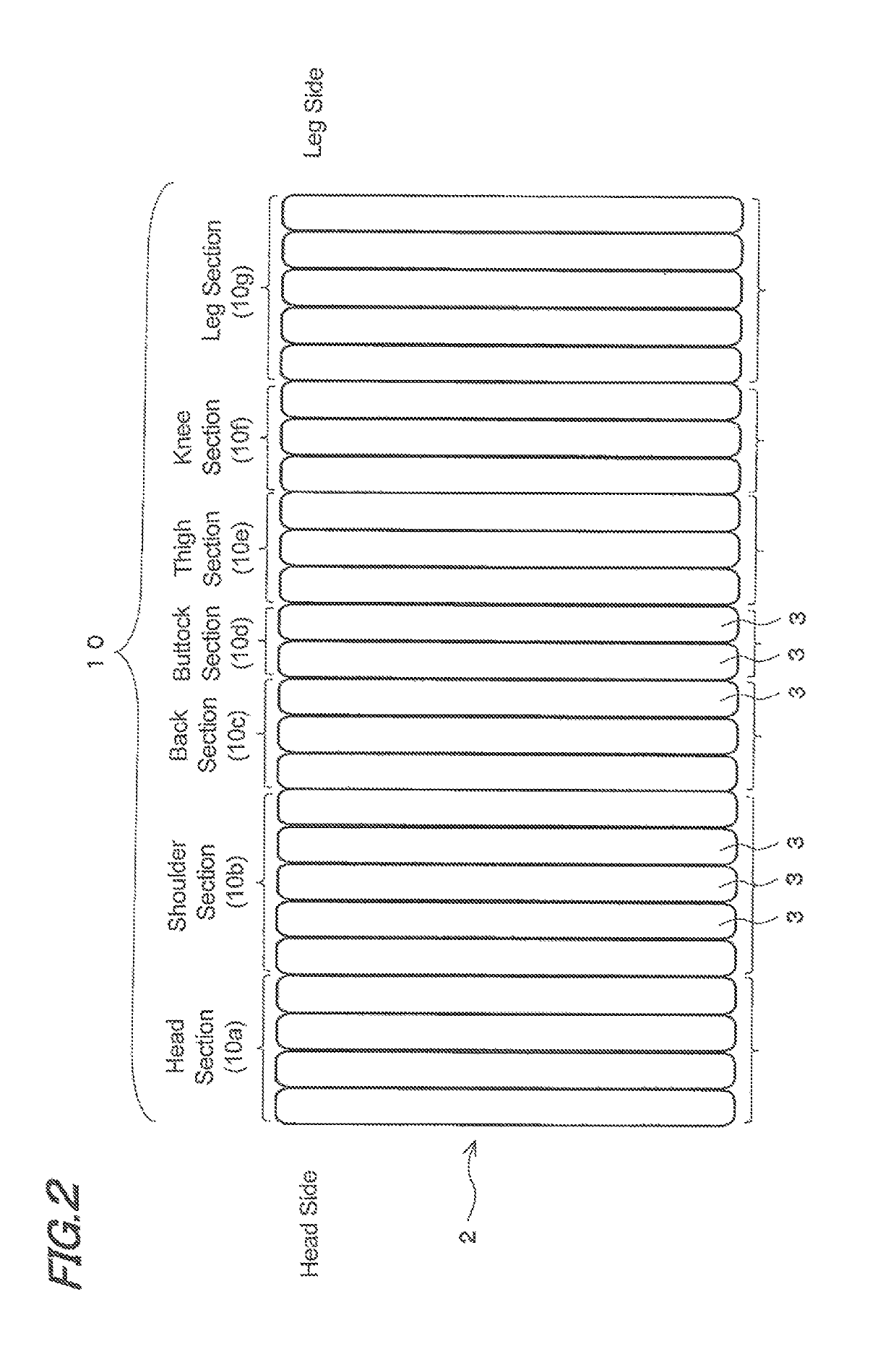
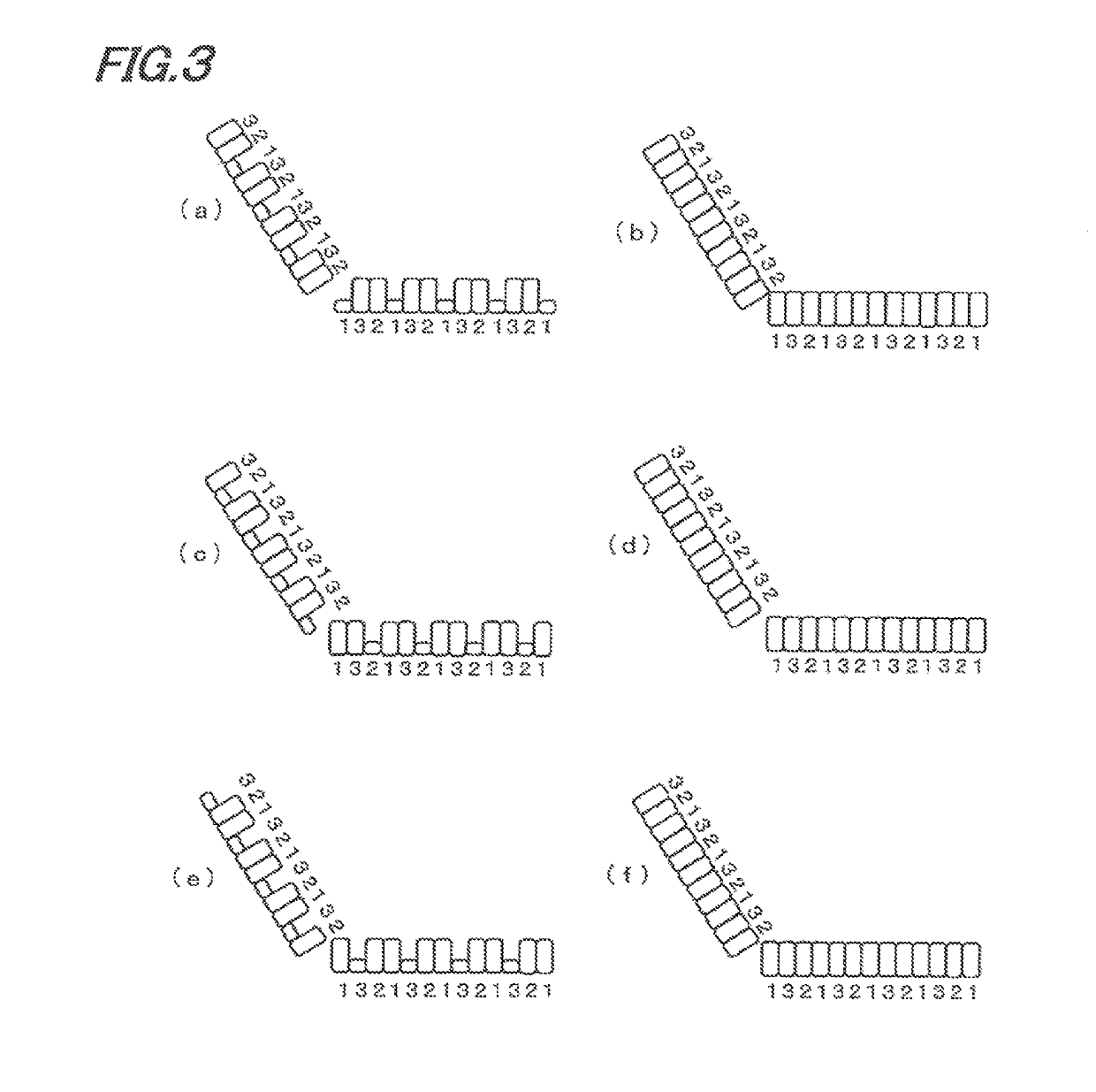
[0060]Now, the embodiment of the present invention will be specifically described with reference to the accompanying drawings. As shown in FIGS. 1 and 2, the present embodiment is an air mattress 2 to be used for a gatch bed. In this gatch bed, a back bottom 1a, hip bottom 1b, buttock bottom 1c, thigh bottom 1d, knee bottom 1e, leg bottom 1f are arranged in the longitudinal direction of the bed. Of these bottoms, the back bottom 1a, thigh bottom 1d and leg bottom 1f can be rotated and moved by means of liking mechanisms and drive cylinders so as to cause the back bottom 1a to perform back-raising and back-lowering operation. The thigh bottom 1d and leg bottom 1f operate subordinately, following raising and lowering motion of the back bottom 1a.

[0061]Placed on these bottoms 1a to 1f is the air mattress 2. As shown in FIG. 2, this air mattress 2 is comprised of a plurality of air cells 3 extended across the bed width, juxtaposed in the longitudinal direction of the bed. Multiple air ...


PUM


Abstract

For each air cell, air is supplied and discharged through one of three lines independent of one another, every third cell being connected to the common line. The control unit controls inflation and deflation of air cells in turn in such an alternate manner that first the pressure of air in the air cells on the first line is increased and decreased, secondly the pressure of air in the air cells on the second line is increased and decreased, then the pressure of air in the air cells on the third line is increased and decreased. Thereafter, when the back tilt angle of the back bottom has reached a predetermined angle or greater, the control unit increases the pressure of air cells whose pressure is being lowered at that moment so as to produce an inflated mode similar to that of the other air cells. Then, while the back bottom is being raised, the control unit performs an inflation and deflation control of individual lines alternately on a cycle shorter than that in a normal control mode. With this arrangement, it is possible to prevent shrinkage of the air mattress in the bed longitudinal direction, prevent the bed user from sliding on the bed, and further prevent the bed user from getting bedsores.

Description

TECHNICAL FIELD[0001]The present invention relates to an air mattress for gatch bed, placed on a plurality of bottoms including a back bottom, a hip bottom and a leg bottom and the like arranged in the bed longitudinal direction to perform a back raising operation and the like, in particular relates to the air mattress for a gatch bed, formed of the plurality of air cells arranged in parallel in a bed longitudinal direction.BACKGROUND ART[0002]In the gatch bed having an air mattress, a back bottom 1a, hip bottom 1b, buttock bottom 1c, thigh bottom 1d, knee bottom 1e, leg bottom 1f are arranged in the longitudinal direction of the bed, as shown in FIG. 1. Of these bottoms, the back bottom 1a, thigh bottom 1d and leg bottom 1d, for example, can be adapted to move up and down to thereby raise the back of the bed user (a person lying on the bed) for easy reading and other purposes or lower the back and flatten the bed for easy sleeping, easy medical examination and other purposes.[0003]...

Claims


Application Information

Patent Timeline
Patent Type & Authority Patents(United States)
IPC IPC(8): A61G7/05A61G7/057A47C27/08A47C27/10
CPCA61G7/05776A47C27/10A47C27/083A47C27/082A61G7/015
Inventor OHNO, KENTAKATO, ATSUSHITACHIKAWA, TOMOKAZU
Owner PARAMOUNT BED CO LTD
Why Eureka
Try Eureka