
Method of calibrating fracture geometry to microseismic events

a microseismic event and fracture geometry technology, applied in the field of fracture operations, can solve the problems of deviating from the drilling plan, affecting the degree of complexity of the resulting fracture network, and difficulty in distinguishing between small scale fracture complexity and simple planar fracture growth

Active Publication Date: 2019-07-16
SCHLUMBERGER TECH CORP
View PDF68 Cites 5 Cited by
  • Summary
  • Abstract
  • Description
  • Claims
  • Application Information

AI Technical Summary

Benefits of technology

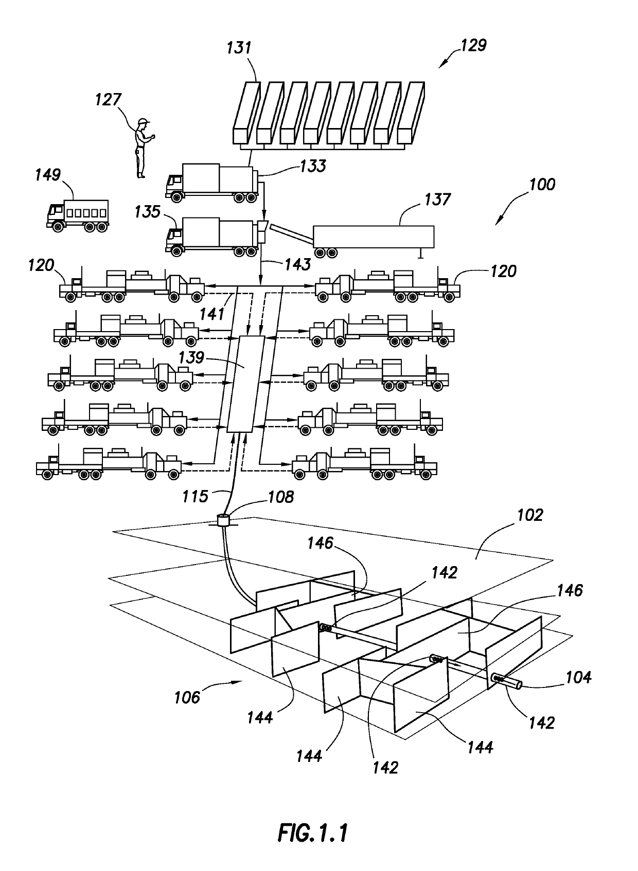
The present disclosure relates to methods for performing fracture operations in subterranean formations. The methods involve obtaining wellsite data including natural fracture parameters and obtaining a mechanical earth model of the subterranean formation. Hydraulic fractures are then extended from the wellbore and into the fracture network using the determined parameters. The fracture growth pattern is determined based on the determined parameters, and the method may be repeated to stimulate the wellsite by injecting an injection fluid with proppant into the fracture network. The methods may also involve validating the fracture growth pattern and repeating the generating process based on the determined parameters. The technical effects of the methods include improved wellbore stimulation and efficient wellbore construction.

Problems solved by technology

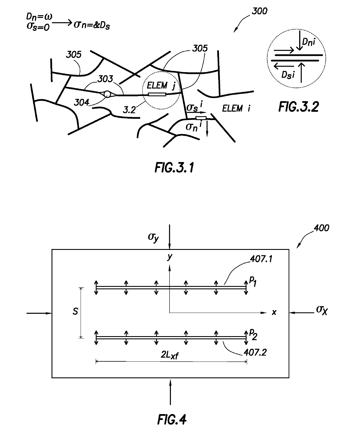
During hydraulic fracturing treatments, geomechanical interactions between hydraulic fractures and natural fractures may have an impact on the degree of complexity of the resulting fracture network.
In some cases, challenges may exist in distinguishing between small scale fracture complexity and simple planar fracture growth.
However, as information is gathered, the drilling operation may to deviate from the drilling plan.
In particular, a portion of the tensile deformation related to opening of fractures may be expected to be aseismic.
The fracture complexity may be difficult to predict a priori, due to reservoir heterogeneity and interactions of treatment and completion designs.
The modeled shear is highest for stage 2, suggesting too much complexity in the simulated fracture network for this stage.
The interaction of the hydraulic fracture and the natural fracture may result in fracture branching where they intersect.

Method used


Image

  • Method of calibrating fracture geometry to microseismic events
  • Method of calibrating fracture geometry to microseismic events
  • Method of calibrating fracture geometry to microseismic events

Examples


example cases

Case #1—Parallel Fractures in Horizontal Wells

[0127]FIG. 8 is a schematic plot 800 of parallel transverse fractures 811.1, 811.2, 811.3 propagating simultaneously from multiple perforation clusters 815.1, 815.2, 815.3, respectively, about a horizontal wellbore 804. Each of the fractures 811.1, 811.2, 811.3 provides a different flow rate q1, q2, q3 that is part of the total flow qt at a pressure p0.

[0128]When the formation condition and the perforations are the same for all the fractures, the fractures may have about the same dimensions if the friction pressure in the wellbore between the perforation clusters is proportionally small. This may be assumed where the fractures are separated far enough and the stress shadow effects are negligible. When the spacing between the fractures is within the region of stress shadow influence, the fractures may be affected not only in width, but also in other fracture dimension. To illustrate this, a simple example of five parallel fractures may be...

case # 2

Case #2—Complex Fractures

[0137]In an example of FIG. 12, the UFM model may be used to simulate a 4-stage hydraulic fracture treatment in a horizontal well in a shale formation. See, e.g., Cipolla, C., Weng, X., Mack, M., Ganguly, U., Kresse, O., Gu, H., Cohen, C. and Wu, R., Integrating Microseismic Mapping and Complex Fracture Modeling to Characterize Fracture Complexity. Paper SPE 140185 presented at the SPE Hydraulic Fracturing Conference and Exhibition, Woodlands, Tex., USA, Jan. 24-26, 2011, (hereinafter “Cipolla 2011”) the entire contents of which are hereby incorporated by reference in their entirety. The well may be cased and cemented, and each stage pumped through three or four perforation clusters. Each of the four stages may include of approximately 25,000 bbls (4000 m3) of fluid and 440,000 lbs (2e+6 kg) of proppant. Extensive data may be available on the well, including advanced sonic logs that provide an estimate of minimum and maximum horizontal stress. Microseismic m...

case # 3

Case #3—Multi-Stage Example

[0141]Case #3 is an example showing how stress shadow from previous stages can influence the propagation pattern of hydraulic fracture networks for next treatment stages, resulting in changing of total picture of generated hydraulic fracture network for the four stage treatment case.

[0142]This case includes four hydraulic fracture treatment stages. The well is cased and cemented. Stages 1 and 2 are pumped through three perforated clusters, and Stages 3 and 4 are pumped through four perforated clusters. The rock fabric is isotropic. The input parameters are listed in Table 4 below. The top view of total hydraulic fracture network without and with accounting for stress shadow from previous stages is shown in FIGS. 13.1-13.4.

[0143]

TABLE 4Input parameters for Case #3Young's modulus4.5 × 106 psi = 3.1e+10 PaPoisson's ratio0.35Rate30.9 bpm = 0.082 m3 / sViscosity0.5 cp = 0.0005 pa-sHeight330 ft = 101 mPumping time70 min

[0144]FIGS. 14.1-14.4 are schematic diagrams ...


PUM


Abstract

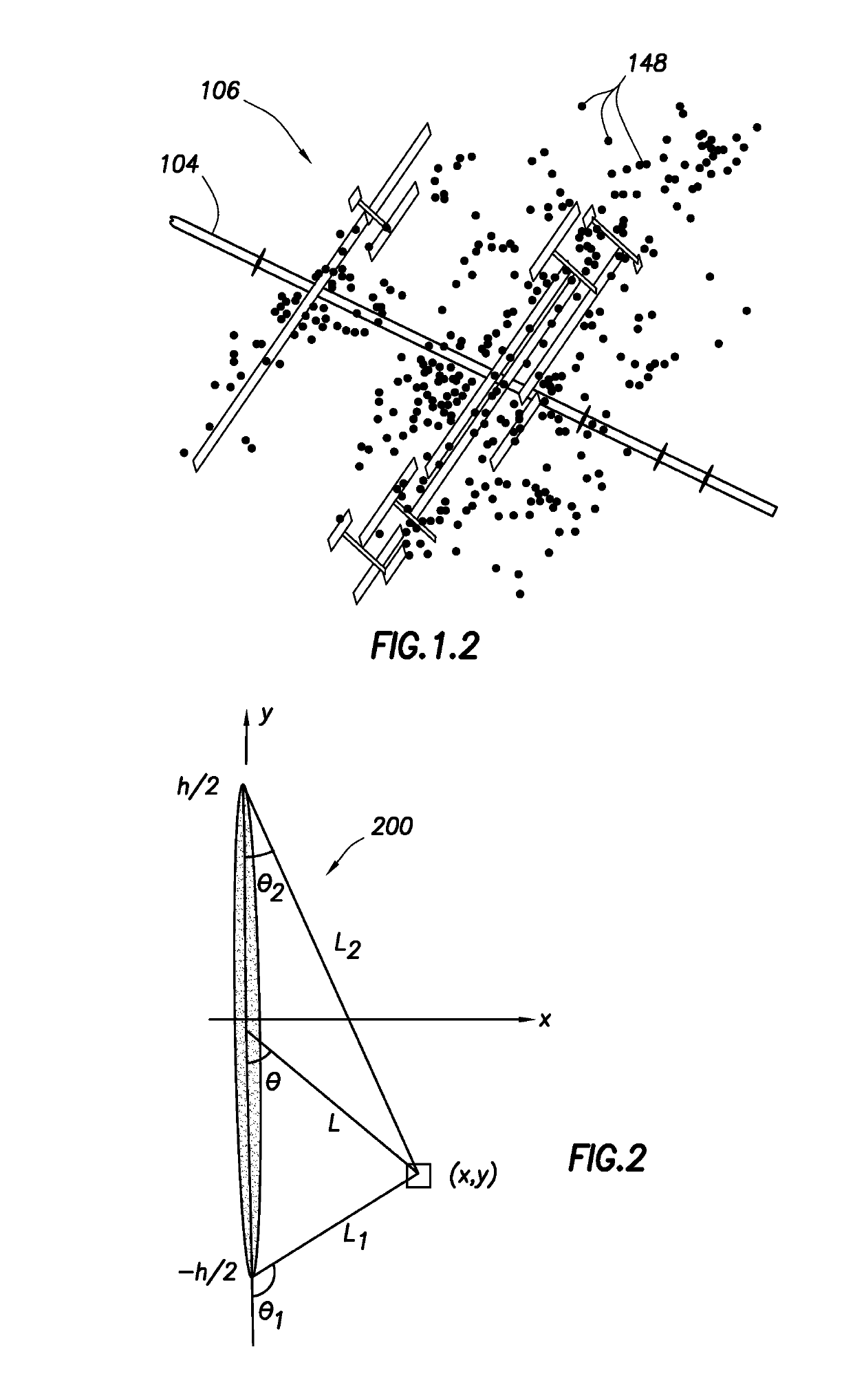
A method of performing a fracture operation is provided at a wellsite. The wellsite is positioned about a subterranean formation having a wellbore therethrough and a complex fracture network therein. The complex fracture network includes natural fractures, and the wellsite stimulated by injection of an injection fluid with proppant into the complex fracture network. The method involves generating wellsite data comprising measurements of microseismic events of the subterranean formation, modeling a hydraulic fracture network and a discrete fracture network of the complex fracture network based on the wellsite data, and performing a seismic moment operation. The method involves determining an actual seismic moment density based on the wellsite data and a predicted seismic moment density based on shear and tensile components of the simulated hydraulic fracture network, and calibrating the discrete fracture network based on a comparison of the predicted moment density and the actual moment density.

Description

CROSS REFERENCE TO RELATED APPLICATION[0001]This application claims priority to U.S. Provisional Application No. 61 / 842,257 filed on Jul. 2, 2013, the entire contents of which are hereby incorporated by reference herein.[0002]This application is also a continuation-in-part of U.S. patent application Ser. No. 14 / 133,687, filed Dec. 19, 2013 which claims priority to U.S. Provisional Application No. 61 / 746,183 filed on Dec. 27, 2012, the entire contents of which are hereby incorporated by reference herein and which is a continuation-in-part of U.S. Patent Application No. 61 / 628,690, filed Nov. 4, 2011, the entire contents of which are hereby incorporated by reference herein.[0003]This application also relates to U.S. Provisional Application Ser. No. 61 / 451,843, filed 11 Mar. 2011, entitled “Method, System, Apparatus And Computer Readable Medium For Unconventional Gas Geomechanics Simulation;” and, this application relates to International Patent Application No. WO2012125558, filed 20 S...

Claims


Application Information

Patent Timeline
IPC IPC(8): E21B43/267
CPCE21B43/267
Inventor MAXWELL, SHAWNWENG, XIAOWEIKRESSE, OLGACIPOLLA, CRAIGMACK, MARKRUTLEDGE, JAMES T.UNDERHILL, WILLIAMGANGULY, UTPAL
Owner SCHLUMBERGER TECH CORP
Learn More