Medical image display apparatus, display control method therefor, and non-transitory recording medium

a display apparatus and medical image technology, applied in the field of medical image diagnosis apparatus, can solve the problems of difficult comparison of paths and the size of cpr images

Active Publication Date: 2019-07-16
CANON KK
View PDF26 Cites 20 Cited by
  • Summary
  • Abstract
  • Description
  • Claims
  • Application Information

AI Technical Summary

Problems solved by technology

However, the technology disclosed in US 2004 / 0249270 and conventional technologies have a problem that the size of a CPR image depends on the display area of the CPR image.
As a result, the paths are difficult to be compared though they are identical.

Method used


Image

  • Medical image display apparatus, display control method therefor, and non-transitory recording medium
  • Medical image display apparatus, display control method therefor, and non-transitory recording medium
  • Medical image display apparatus, display control method therefor, and non-transitory recording medium

Examples


first embodiment

[0036]Embodiments of the present invention will be described in detail below with reference to drawings. A first embodiment will be described first.

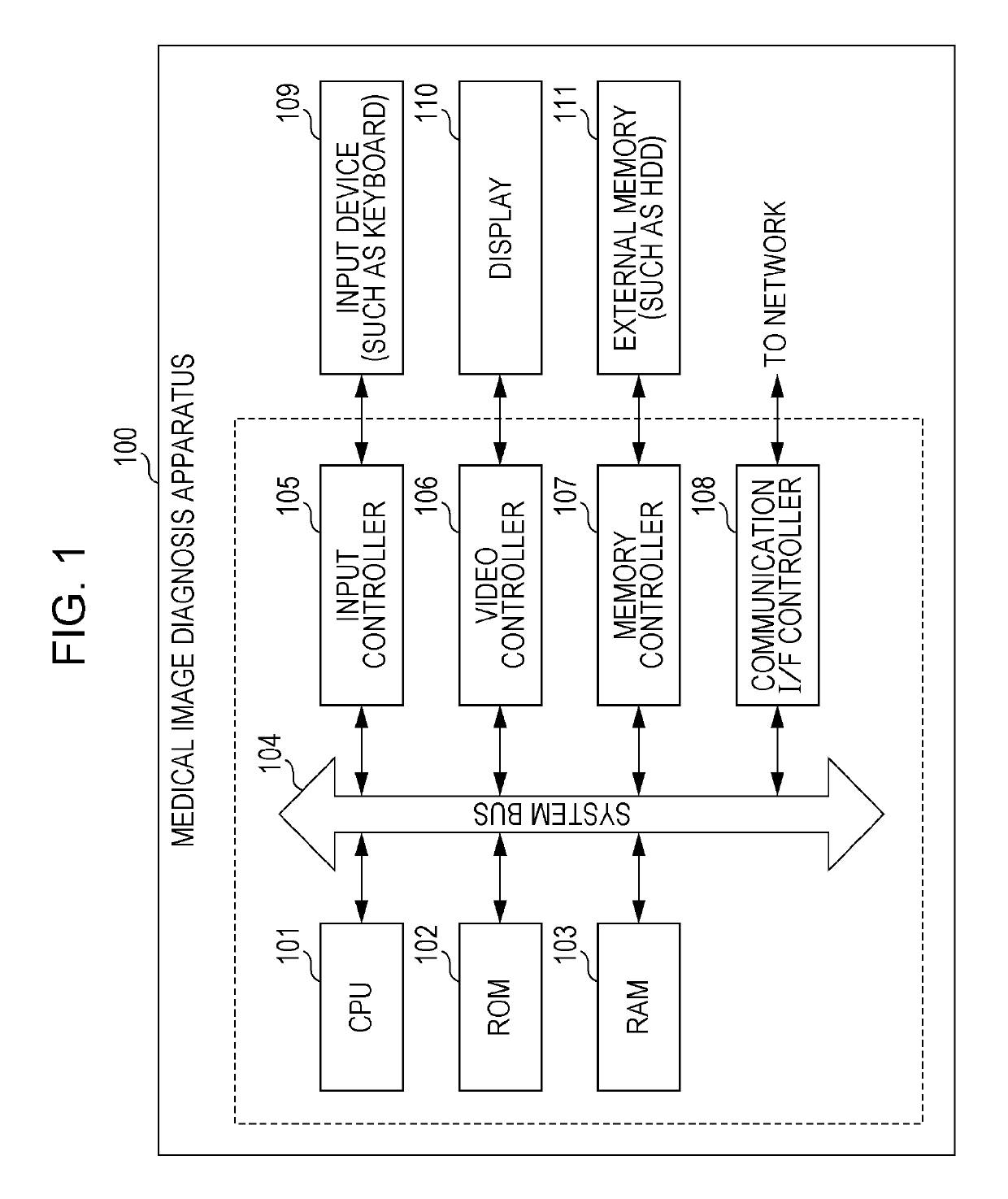
[0037]FIG. 1 illustrates an example of a hardware configuration of a medical image diagnosis apparatus 100. It should be understood that the hardware configuration of the medical image diagnosis apparatus 100 is not limited to the one illustrated in FIG. 1.

[0038]The medical image diagnosis apparatus 100 is configured to generate a three-dimensional medical image from CT or MRI two-dimensional medical images and generate a CPR image by identifying a tubular structure from the three-dimensional medical image. The medical image diagnosis apparatus 100 may be a so-called personal computer or may be a server apparatus. The medical image diagnosis apparatus 100 may be a tablet terminal or a mobile terminal having a touch panel.

[0039]A CPU 101 generally controls devices and controllers connected to a system bus 104.

[0040]A ROM 102 or an externa...

second embodiment

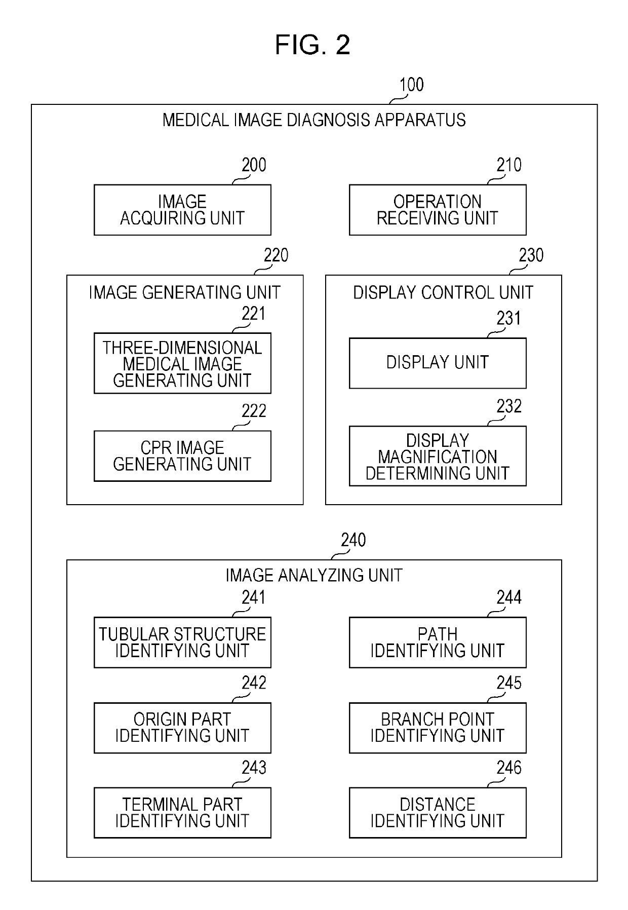
[0113]FIG. 17 illustrates an example of a functional configuration of the medical image diagnosis apparatus 100 according to the The functions illustrated in FIG. 17 are components implemented by the hardware and programs illustrated in FIG. 1. It should be understood that the functional configuration of the medical image diagnosis apparatus 100 is not limited thereto. The descriptions regarding the same functions as those in FIG. 2 will be omitted.

[0114]The medical image diagnosis apparatus 100 further includes a setting unit 1700 in addition to the functional units illustrated in FIG. 2. The setting unit 1700 is a functional unit configured to set operations to be performed in the medical image diagnosis apparatus 100. The setting unit 1700 generates a dialog (or window) for changing a setting, displays it by means of the function of the display unit 231 and stores a setting received in the operation receiving unit 210 in the external memory 111 or RAM 103. A setting stored there...


PUM


Abstract

A medical image display apparatus includes a display unit that displays at least partial paths of a plurality of paths of a tubular structure identified from a medical image, the at least partial paths including a first path and a second path that are displayed separately from each other, and a display magnification determining unit that determines at least one of a display magnification and a display position of at least one of the displayed first and second path based on whether the first path and the second path has a common part to each other, wherein the display unit displays the first path and the second path and displays one of the first path and the second path at a determined display magnification.

Description

BACKGROUND[0001]Field[0002]Aspects of the present invention generally relate to a medical image diagnosis apparatus that displays at a proper display magnification a path including a branch point identical to that of another path in a tubular structure when the paths are displayed, a control method therefor, and a program.[0003]Description of the Related Art[0004]A medical-image display mechanism exists which displays a tubular structure such as a blood vessel and the intestines as a three-dimensional medical image acquired by performing volume rendering by superimposing two-dimensional medical images of X-ray CT or MRI, for example.[0005]Curved Multi Planer Reconstruction (hereinafter, CPR) is a technology for reconstructing multiple planes of a three-dimensional medical image. U.S. Patent Application Publication No. 2004 / 0249270 discloses a technology which generates a straightened CPR image acquired by drawing a curved line along a centerline of a tubular structure in a longitudi...

Claims


Application Information

Patent Timeline
Patent Type & Authority Patents(United States)
IPC IPC(8): G09G5/00G09G5/373A61B6/00G09G5/38G06T19/00G06T3/40G09G3/00A61B6/03
CPCG06T3/40A61B6/466A61B6/504A61B6/5217A61B6/5223G06T19/00G09G5/373G09G5/38A61B6/463G09G2380/08A61B6/032G06T2210/41G06T2219/028G09G3/003G09G2340/02G09G2340/045A61B6/03A61B6/462A61B6/464A61B6/48A61B6/5211G06T15/08G16H50/30
Inventor SAKAMOTO, TSUYOSHI
Owner CANON KK
Why Eureka
Try Eureka