Supercharge Your Innovation With Domain-Expert AI Agents!

Suture attachment apparatus

a technology of suture attachment and suture, which is applied in the field of bone screws, can solve the problems of failure of the prosthesis, bone loss, and inability to adapt to the permanent anchorage of the artificial acl replacement,

Active Publication Date: 2019-07-23
KYON
View PDF79 Cites 0 Cited by
  • Summary
  • Abstract
  • Description
  • Claims
  • Application Information

AI Technical Summary

Benefits of technology

The invention is a screw and peg system for repairing bones, including a screw with a central axis hole and a head above it. The head has a slot between the hole and the post. The central axis hole is shaped to hold a suture. A peg is insertable into the central axis hole and can hold the suture within it. The suture can be looped around the peg or tied in a knot with the peg. The invention also includes a suture that is formed into a loop with fused filaments and a suture that has longer filaments fused beyond the fused portion. This system provides a stable and secure way to repair bones.

Problems solved by technology

Neither of these techniques is suitable for a permanent anchorage of an artificial ACL replacement.
Bending of the prosthesis over the edge of the hole will lead to both, bone loss due to contact resorption and mechanical damage—ultimately failure—of the prosthesis due to bending and wear at the edge of the hole.
However, sometimes the knot may pass through the central hole causing the ACL prosthesis to loosen or fail.
Additionally, tying the knot can be difficult while retaining the ACL prosthesis taut.

Method used


Image

  • Suture attachment apparatus
  • Suture attachment apparatus

Examples


Embodiment Construction

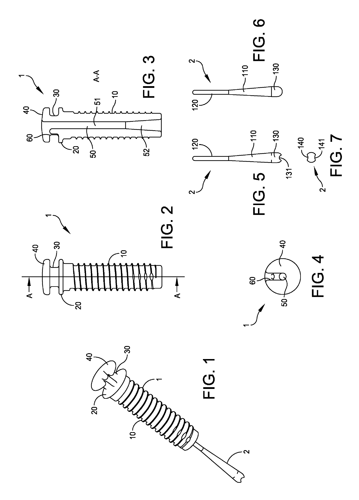
[0021]FIG. 1 illustrates a bone screw or anchor 1 and peg 2 for holding a suture according to an embodiment of the present invention. FIGS. 2-4 are various views of bone screw. FIGS. 5-7 are various views of the peg.

[0022]The bone screw 1 of the present invention allows for attachment of a lateral suture. The bone screw includes a body 10 having threads thereon. The body 10 can be threaded into a hole drilled into a bone. A suture can be attached to the bone screw 1 as set forth herein. At the top of the body 10 is a base 20. When screwed into the bone, the base 20 abuts the surface of the bone. A post 30 extends from the base 20. A head 40 is positioned on the post opposite the base 30. The base 20 and head 40 have a diameter wider than the post 30. The suture wraps around the post 30 and is held in place by the base 20 and head 40. A central axis hole 50 extends within the head 40, post 30, base 20 and body 10 of the screw 1. A slot 60 is formed in the head 40 from the central axi...


PUM


Abstract

A bone anchor has a central bore allowing for uniquely attaching a suture thereto. The bore is shaped so that it is wider at the bottom of the anchor than at the top of the anchor. A peg fits within the bore. The suture is looped around the peg and the peg is inserted into the bore. Friction between the bore, peg and suture holds the suture in place. A suture for use with the bone anchor may be formed by fusing together the ends of a plurality of fibers to form a loop.

Description

CROSS-REFERENCE TO RELATED APPLICATIONS[0001]The present application is a U.S. national phase application, filed in accordance with 35 U.S.C. § 371, of International Application No. PCT / US2010 / 031656, which was filed Apr. 19, 2010, and which claims the benefit of the filing date of U.S. Provisional Application No. 61 / 170,623, which was filed Apr. 19, 2009. The content of these priority applications is hereby incorporated by reference herein in its entirety.TECHNICAL FIELD (FIELD OF THE INVENTION)[0002]The present invention relates to a bone screw and a method and apparatus for attaching sutures to a bone screw or bone anchor. More particularly, it relates to a method and apparatus for attaching a suture to a bone screw or bone anchor having a central hole.BACKGROUND OF THE INVENTION[0003]There are a variety of anchors used to fix the ends of an ACL prosthesis into bones. Most commonly, they are so-called interference screws, designed to be inserted along the prosthesis (transplanted...

Claims


Application Information

Patent Timeline
Patent Type & Authority Patents(United States)
IPC IPC(8): A61B17/04A61B17/06
CPCA61B17/0401A61B17/06166A61B2017/0619A61B2017/0451A61B2017/044
Inventor TEPIC, SLOBODAN
Owner KYON
Features
  • R&D
  • Intellectual Property
  • Life Sciences
  • Materials
  • Tech Scout
  • Unparalleled Data Quality
  • Higher Quality Content
  • 60% Fewer Hallucinations
Learn More