Vehicle speaker system

a speaker system and vehicle technology, applied in the direction of loudspeaker screens, transducer details, vehicle components, etc., can solve the problems of reducing the reliability of the speaker, affecting the acoustic characteristics, and the speaker cannot exhibit its original performance, so as to reduce the influence of obstacles, the structure as the speaker system is simple, and the effect of reducing the influen

Active Publication Date: 2019-07-23
ALPINE ELECTRONICS INC
View PDF16 Cites 0 Cited by
  • Summary
  • Abstract
  • Description
  • Claims
  • Application Information

AI Technical Summary

Benefits of technology

[0005]The present disclosure has been made in view of these circumstances of the related art, and an object of the disclosure is to provide a vehicle speaker system including a speaker mounted on a vehicle partition, which separates an engine compartment and a vehicle cabin, and configured to emit a positive-phase sound pressure into the vehicle cabin and to exhaust a reverse-phase sound pressure to the engine compartment. In this vehicle speaker system, the speaker can be prevented from being influenced by heat from the engine compartment and wind pressure associated with vehicle running, and a back pressure is sufficiently removed to reduce the influence on the acoustic characteristics.

Problems solved by technology

In such a condition, reliability of the speaker is reduced and the speaker cannot exhibit its original performance (acoustic characteristics).
Although it is conceivable to dispose, for example, a small enclosure behind the speaker for protection, a back pressure is insufficiently removed and this may adversely affect the acoustic characteristics.
Heat generated from the engine, especially an engine block, may reach the speaker and deteriorate the members that constitute the speaker.
Such an obstacle (for example, heat and foreign matter) from the obstacle generation source obstructs a normal operation of the speaker.
If the shield member forms a closed space between the shield member and the speaker, the acoustic characteristics of the speaker may be adversely affected.
A section of the diaphragm near the center portion is most susceptible to the influence of wind pressure and heat.

Method used


Image

  • Vehicle speaker system
  • Vehicle speaker system
  • Vehicle speaker system

Examples


Embodiment Construction

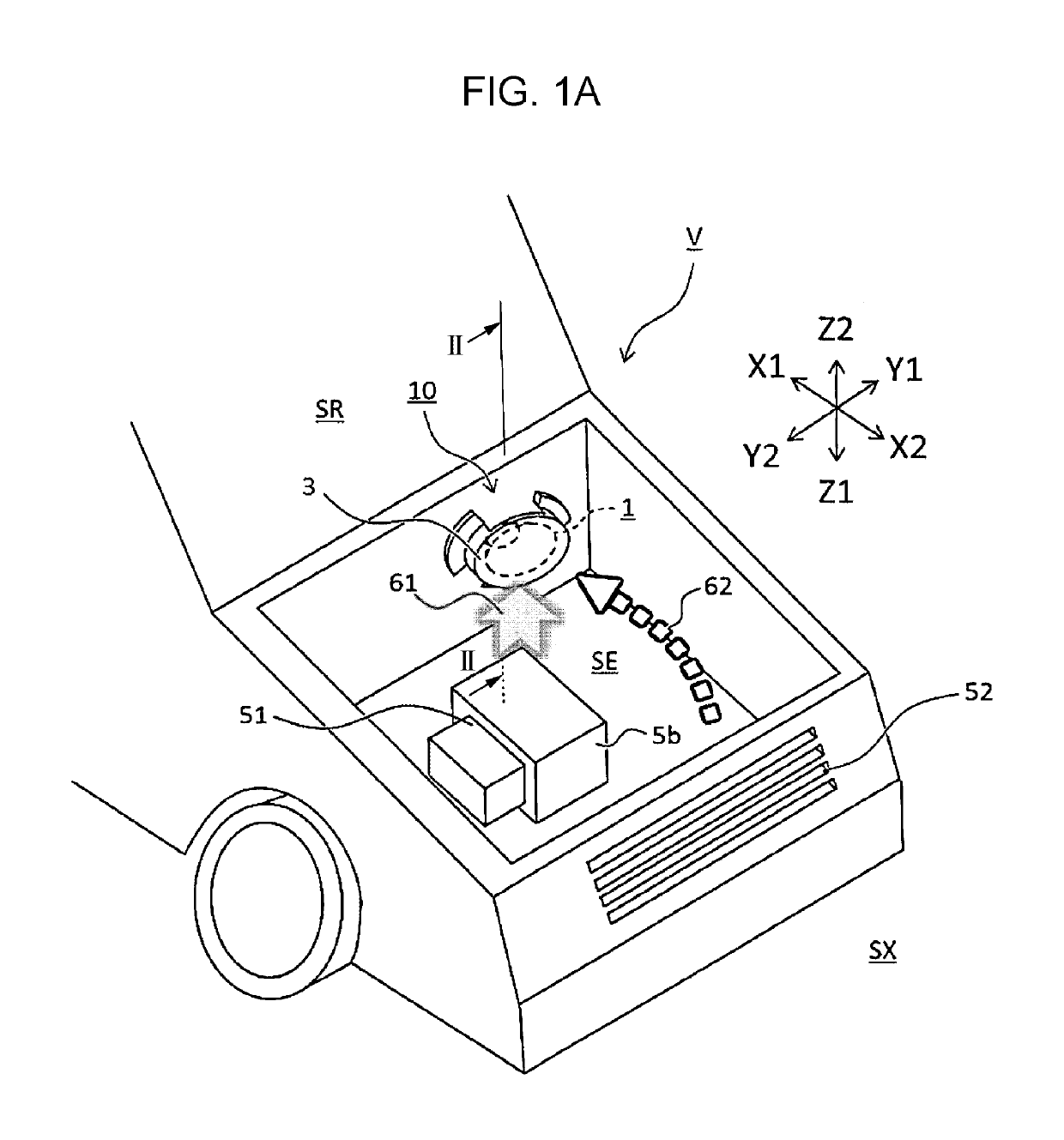
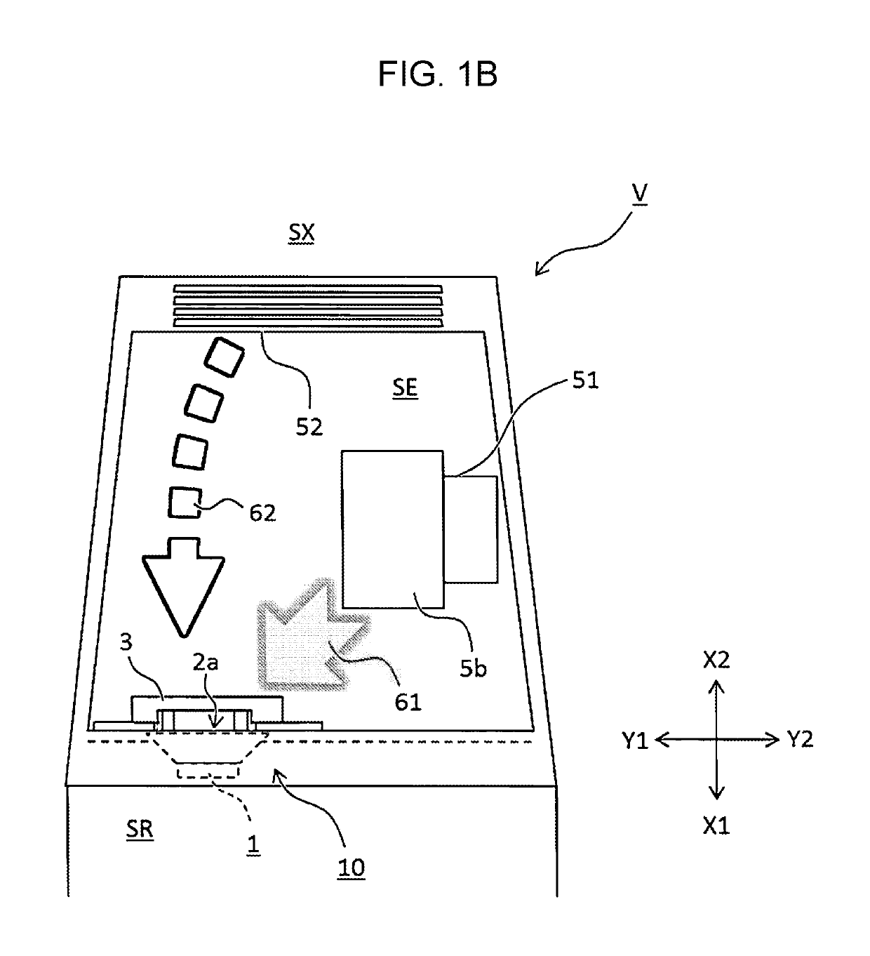
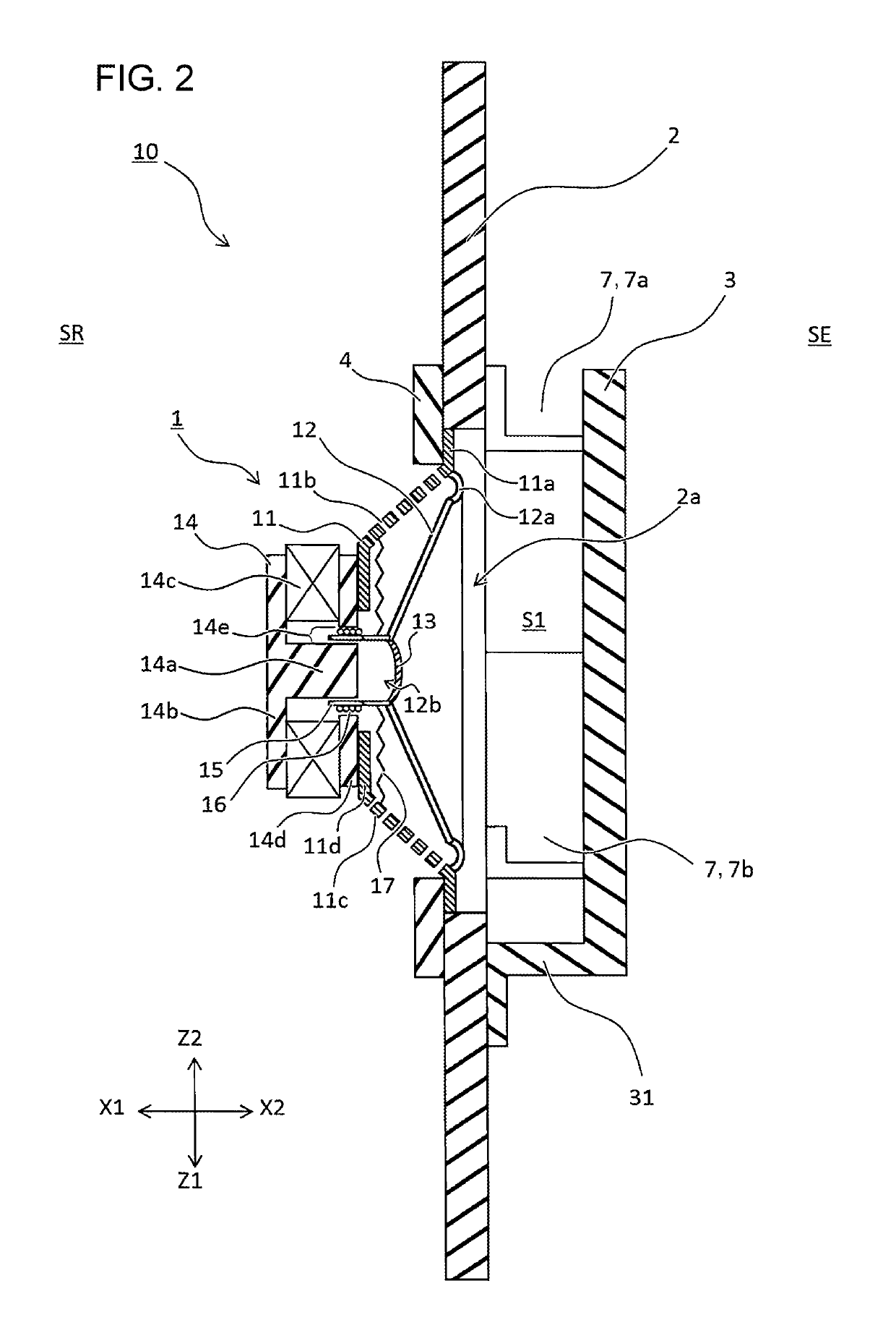
[0026]Embodiments of the present invention will be described below with reference to the drawings. FIGS. 1A and 1B are a perspective view and a top view, respectively, conceptually illustrating a structure of a vehicle quipped with a vehicle speaker system according to an embodiment of the present invention. FIG. 2 is a cross-sectional view taken along line II-II in FIG. 1A.

[0027]As illustrated in FIG. 2, a vehicle speaker system 10 according to an embodiment of the present invention includes a speaker 1. In the speaker 1, various members are attached to a frame 11 generally shaped like a truncated cone. The frame 11 includes an annular portion 11a on an outer peripheral side and a spoke-shaped support portion 11c extending from the annular portion 11a. For convenience, the support portion 11c is shown by dotted lines to have cut holes 11b in the drawings.

[0028]In the speaker 1, a diaphragm 12 for generating sound pressure is generally shaped like a truncated cone, and has an edge 1...


PUM


Abstract

A vehicle speaker system includes a speaker having a diaphragm that generates a sound pressure, a frame that supports the diaphragm vibratably, and a driving unit attached to the frame to drive the diaphragm. A position of the speaker relative to a partition separating a vehicle-cabin inner space and an engine compartment inner space is determined so that the sound pressure generated by an action of the diaphragm passes through an opening in the partition. A shield member is provided with at least a part thereof being located between the speaker and an obstacle generation source located in the engine compartment inner space to obstruct an operation of the speaker. An open part allowing a first space provided between the speaker and the shield member to communicate with the engine compartment inner space is provided in such a direction as not to be directed toward the obstacle generation source.

Description

RELATED APPLICATION[0001]The present application claims priority to Japanese Patent Application Number 2017-001112, filed Jan. 6, 2017, the entirety of which is hereby incorporated by reference.BACKGROUND1. Field of the Invention[0002]The present invention relates to a vehicle speaker system that allows stable operation of a speaker mounted in a partition between an engine compartment and a vehicle cabin.2. Description of the Related Art[0003]In speaker systems installed in vehicles (vehicle speaker systems), various methods for improving the quality of sound emitted in a vehicle cabin have been proposed. For example, in an on-vehicle composite speaker apparatus proposed in PTL 1 (Japanese Unexamined Utility Model Registration Application Publication No. 1-126679), a main speaker is mounted at a front opening of a cabinet, a rear opening of the cabinet is covered with a bass-sound auxiliary speaker to form a closed acoustic space therebetween, and a back surface of the auxiliary spe...

Claims


Application Information

Patent Timeline
Patent Type & Authority Patents(United States)
IPC IPC(8): B60R11/02H04R1/02
CPCB60R11/0217H04R1/023H04R1/028H04R1/025H04R2499/13H04R1/021
Inventor TANABE, KEI
Owner ALPINE ELECTRONICS INC
Why Eureka
Try Eureka