Motor-operated compressor

a motor-operated compressor and compressor technology, which is applied in the direction of machines/engines, rotary/oscillating piston pump components, liquid fuel engines, etc., can solve the problems of increasing friction loss, difficult to quickly secure back pressure, and difficulty in maintaining back pressure. , to achieve the effect of suppressing friction loss, suppressing compression loss, and maintaining required back pressur

Inactive Publication Date: 2020-03-12
LG ELECTRONICS INC
View PDF0 Cites 0 Cited by
  • Summary
  • Abstract
  • Description
  • Claims
  • Application Information

AI Technical Summary

Benefits of technology

[0036]In a motor-operated compressor according to the present invention, since pressure of a back pressure space interacts with pressure of a compression chamber, the pressure of the back pressure space can vary according to the change in the pressure of the compression chamber, thereby maintaining required back pressure. This may result in suppressing friction loss that may occur when the pressure of the back pressure space is higher than the required back pressure, and suppressing compression loss that may occur when the back pressure is lower than the required back pressure.
[0037]In addition, in a motor-operated compressor according to the present invention, since a back pressure space is formed between a second scroll and a balance weight, a volume of the back pressure space decreases, thereby forming required back pressure quickly and enhancing compressor efficiency. Also, a back pressure hole communicates with a compression chamber that forms discharge pressure or a compression chamber immediately before a discharge chamber, so that the required back pressure can be secured more quickly even if the volume of the back pressure space is decreased. Furthermore, a radial area of the back pressure space is wider than that of the compression chamber communicating with the back pressure space, resulting in stably supporting an orbiting scroll.
[0038]Furthermore, in a motor-operated compressor according to the present invention, since a main bearing that supports a rotation shaft is installed outside of a back pressure space, load generated by high pressure in the back pressure space is not directly applied to the main bearing, thereby extending lifespan of the main bearing.
[0039]In addition, in a motor-operated compressor according to the present invention, sealing force of a sealing member forming a back pressure space can be improved by supporting the sealing member axially by a pressure hole communicating with a compression chamber. Accordingly, the back pressure space can be effectively sealed even when a high-pressure refrigerant such as a CO2 refrigerant is used, which may result in securing required back pressure smoothly.

Problems solved by technology

As a result, when the back pressure is higher than required back pressure, friction loss increases due to excessive adhesion between the two scrolls.
On the other hand, when the back pressure is lower than the required back pressure, compression loss may occur due to excessive spacing between the two scrolls.
As a result, it is hard to quickly secure the back pressure at the beginning of operation.
However, due to this structure, an excessive load caused by the pressure of the back pressure space is applied to the main bearing, thereby decreasing lifespan of the main bearing.
However, it may cause difficulty in securing required sealing force if the pressure in the back pressure space rises excessively.
In particular, even in the case of a high-pressure refrigerant such as a CO2 refrigerant in which back pressure rises up to 60 to 70 bar, behavior of the orbiting scroll may be made unstable as the back pressure space is not effectively sealed.

Method used


Image

  • Motor-operated compressor
  • Motor-operated compressor
  • Motor-operated compressor

Examples


Embodiment Construction

[0048]Description will now be given in detail of a motor-operated compressor according to exemplary embodiments disclosed herein, with reference to the accompanying drawings.

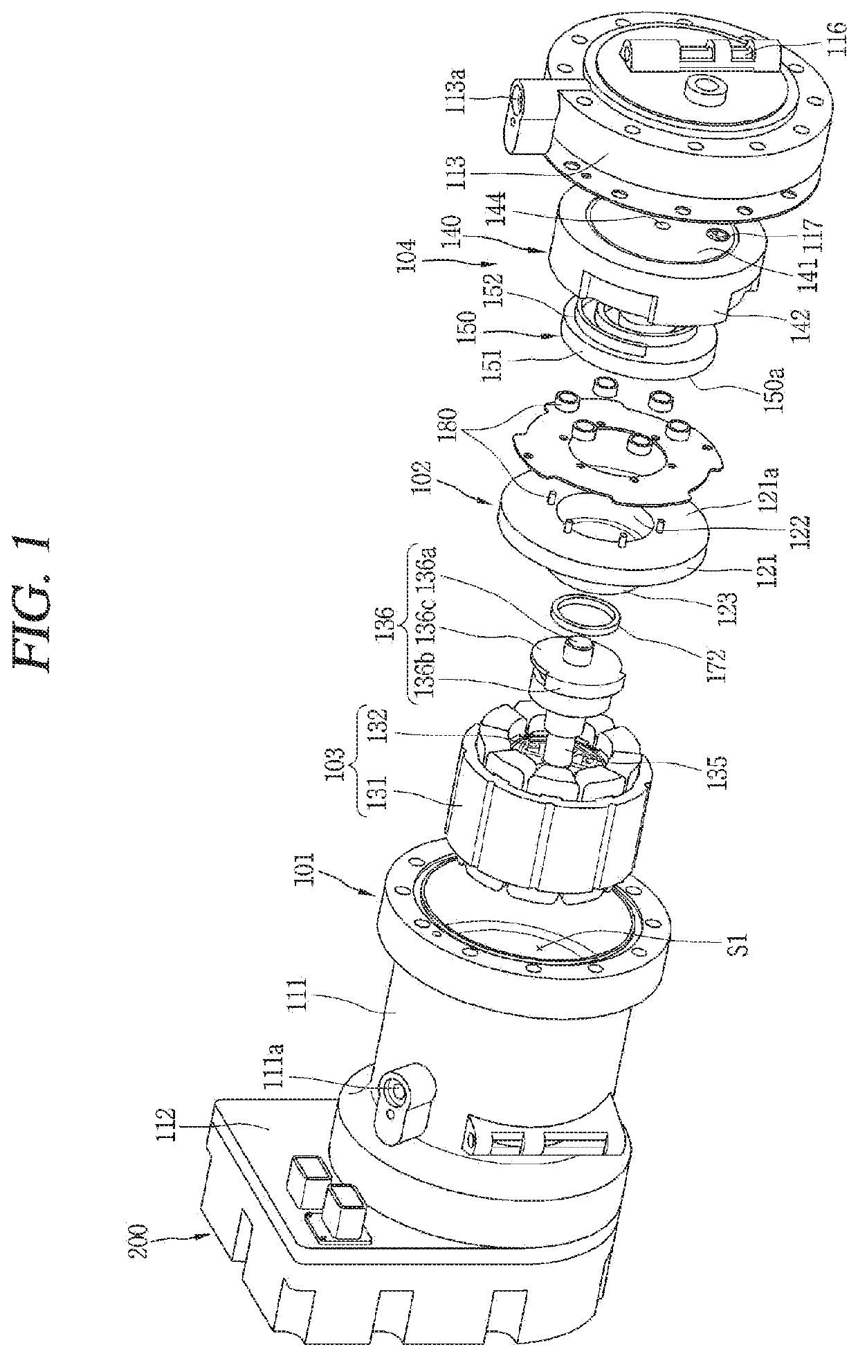
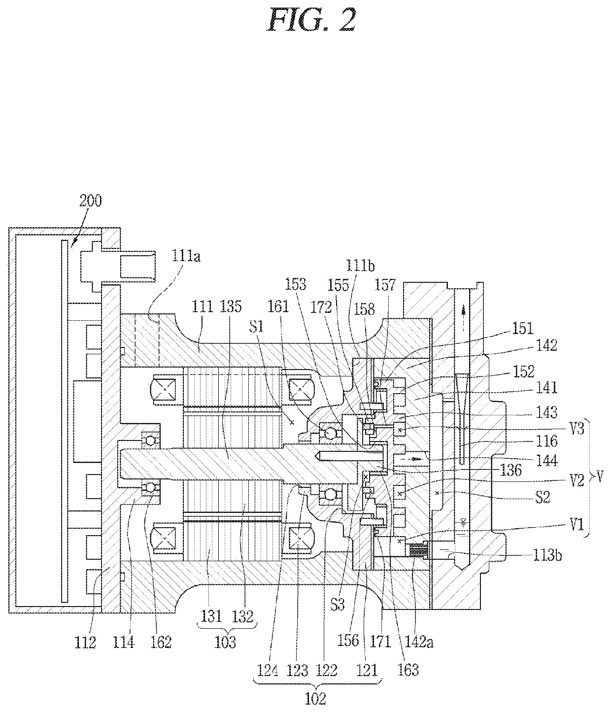
[0049]A motor-operated compressor according to the present invention is a part of a refrigeration cycle apparatus which sucks and compresses a refrigerant, namely, a scroll compressor, in which two scrolls are engaged with each other to compress a refrigerant. This embodiment of the present invention illustrates a high-temperature and high-pressure motor-operated scroll compressor that uses a carbon dioxide (CO2) refrigerant having discharge pressure of 100 bar, more precisely, of about 130 bar and a discharge temperature of about 170° C. FIGS. 1 and 2 are an exploded perspective view and an assembled sectional view of a motor-operated compressor according to the present invention.

[0050]Referring to FIGS. 1 and 2, a motor-operated compressor according to this embodiment may include a casing 101, a main frame 102...


PUM


Abstract

A motor-operated compressor includes a casing having a motor chamber that accommodates a driving motor. The compressor also includes a frame. A first scroll having a first spiral wrap is connected to one side of the frame. A second scroll is provided between the frame and the first scroll. The second scroll has a second spiral wrap that engages with the first spiral warp to form compression chambers between the first and second spiral wraps. The compressor also includes a rotation shaft connected at one end to the driving motor and at an opposite end to the second scroll. The compressor includes a back pressure space defined by a balance weight axially separated from a rear surface of the second scroll. A back pressure passage fluidly connects the compression chambers with the back pressure space.

Description

CROSS-REFERENCE TO RELATED APPLICATION[0001]Pursuant to 35 U.S.C. § 119(a), this application claims the benefit of earlier filing date and right of priority to Korean Application No. 10-2018-0106673, filed on Sep. 6, 2018, the contents of which is incorporated by reference herein in its entirety.BACKGROUND OF THE DISCLOSURE1. Field of the Disclosure[0002]The present invention relates to a scroll type motor-operated compressor.2. Background Art[0003]Generally, compressors for compressing a refrigerant in automotive air conditioning systems have been developed in various forms. Recently, motor-operated compressors driven by electric power using motors have been actively developed according to the tendency of electricization of electric parts of vehicles.[0004]A motor-operated compressor mainly employs a scroll compression method suitable for a high compression ratio operation. In the scroll type motor-operated compressor (hereinafter, abbreviated as ‘motor-operated compressor’), a mot...

Claims


Application Information

Patent Timeline
Patent Type & Authority Applications(United States)
IPC IPC(8): F04C18/02F04C29/12F04C27/00F04C29/00
CPCF04C27/005F04C2250/10F04C18/0215F04C29/12F04C2250/20F04C29/0021F04C18/0246F04C2240/40F04C18/0261F04C27/001F04C29/0071F04C2240/30F04C2240/807F04C28/22F04C29/028F04C2240/50F04C18/0253
Inventor PARK, ILYOUNGMOON, JEHYEONLIM, JUNYOUNGJOO, SANGHYUN
Owner LG ELECTRONICS INC
Why Eureka
Try Eureka