Vane rotary compressor

a compressor and rotary technology, applied in the field of compressors, can solve the problems of increasing suction loss and compression loss, generating more noise from the compressor by vane vibration, and reducing the efficiency of compressors, so as to reduce vibration noise, maintain back pressure, and reduce refrigerant leakage. effect of leakag

Active Publication Date: 2020-05-21
LG ELECTRONICS INC
View PDF0 Cites 7 Cited by
  • Summary
  • Abstract
  • Description
  • Claims
  • Application Information

AI Technical Summary

Benefits of technology

[0037]A vibration distance of the vane can be minimized while maintaining back pressure by optimizing the length of the vane, thereby reducing refrigerant leakage, vibration noise, and abrasion.
[0038]Further, the vibration distance of the vane can be minimized while maintaining the back pressure by forming a surface that limits the vibration distance of the vane between the roller and the vane. This may result in reducing refrigerant leakage, vibration noise and abrasion.
[0039]The vibration distance of the vane can be minimized while maintaining the back pressure by providing a member on the roller for supporting the vane, thereby reducing refrigerant leakage, vibration noise, and abrasion.
[0040]In the vane rotary compressor according to the present disclosure, the back pressure pocket communicating with the back pressure chamber provided at the rear side of the vane is formed in a semi-open shape so that uniform back pressure can be formed at the rear surface of the vane. As a result, the vibration distance can be minimized while suppressing the vane vibration.
[0041]In addition, the vane rotary compressor according to the present disclosure optimizes the vibration distance of the vane even when using a high-pressure refrigerant such as R32, R410, or CO2, which may result in suppressing the vane vibration and minimizing the vibration distance. Therefore, leakage between compression chambers can be prevented and behavior of the vane can be stabilized, thereby enhancing reliability of the vane rotary compressor using the high-pressure refrigerant.
[0042]Furthermore, in the vane rotary compressor according to the present disclosure, the aforementioned effects can be achieved even under a low-temperature heating condition, a high-pressure ratio condition, and a high-speed operation condition.

Problems solved by technology

As a result, a refrigerant in a discharge chamber flows into a suction chamber, causing suction loss and compression loss.
In addition, the inner circumferential surface of the cylinder gets hit by the vane while the vane vibration occurs, which causes abrasion on the inner circumferential surface of the cylinder or the front surface of the vane, leading to a further increase in the suction loss and compression loss.
Also, the vane vibration generates more noise from the compressor.
If the back pressure is increased in order to prevent the vane from being pushed backwards, contact force between the vane and the cylinder increases over an entire section of a compression stroke, thereby increasing friction loss.
Further, in the related art vane rotary compressor, pressure of oil supplied to the rear surface of the vane is not even, which causes pressure pulsation.
As a result, inconsistent back pressure is formed on the rear surface of the vane, thereby further increasing the vane vibration and simultaneously extending a vibration distance of the vane.
This may be particularly problematic when a high-pressure refrigerant such as R32, R410a, or CO2 is used.
As a result, a bearing surface on the rotation shaft is reduced, which makes behavior of the rotation shaft more unstable, leading to a further increase in mechanical friction loss.

Method used


Image

  • Vane rotary compressor
  • Vane rotary compressor
  • Vane rotary compressor

Examples


Embodiment Construction

[0054]Description will now be given in detail of a vane rotary compressor according to exemplary embodiments disclosed herein, with reference to the accompanying drawings.

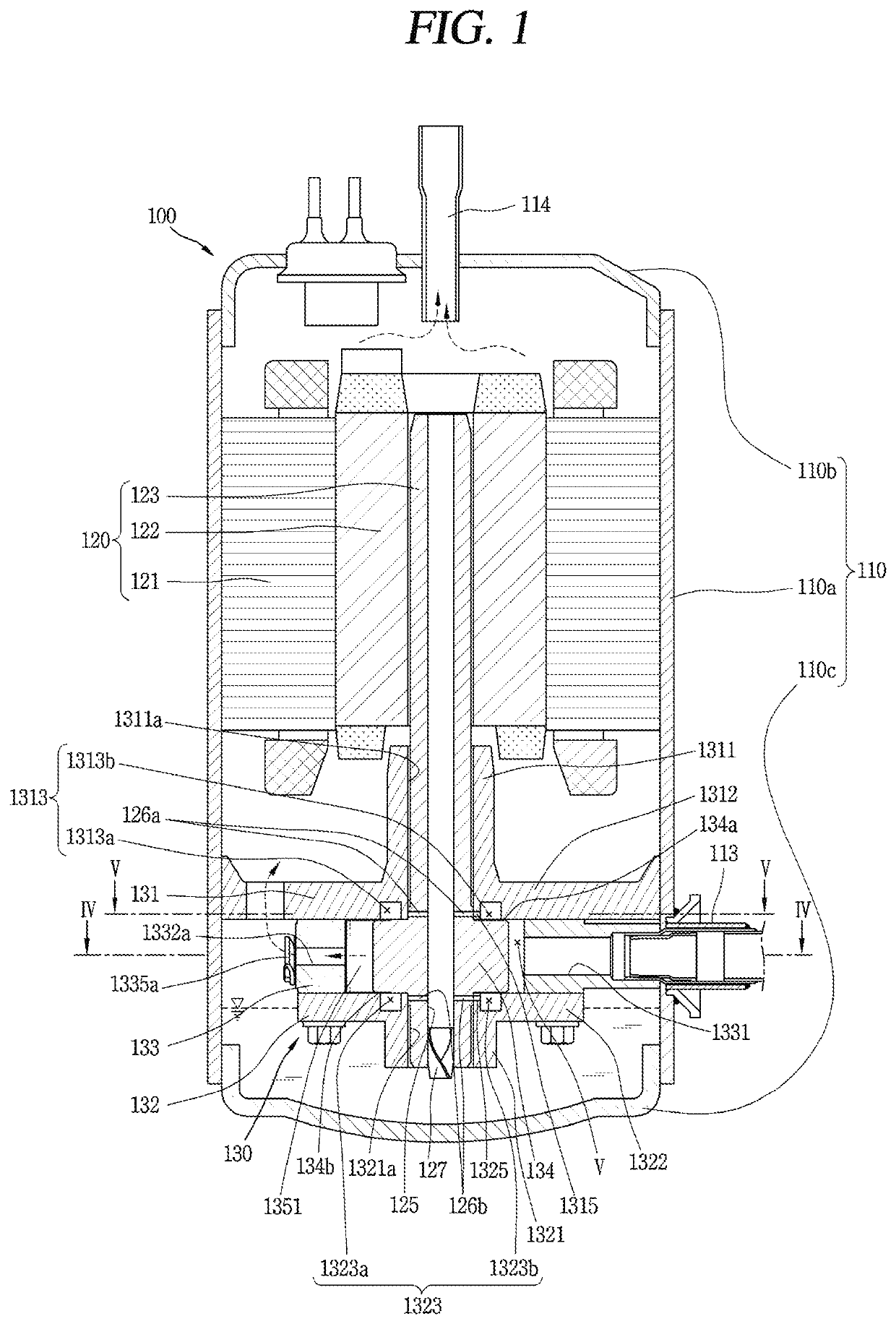
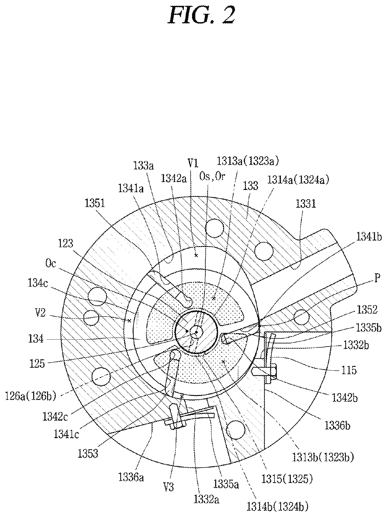
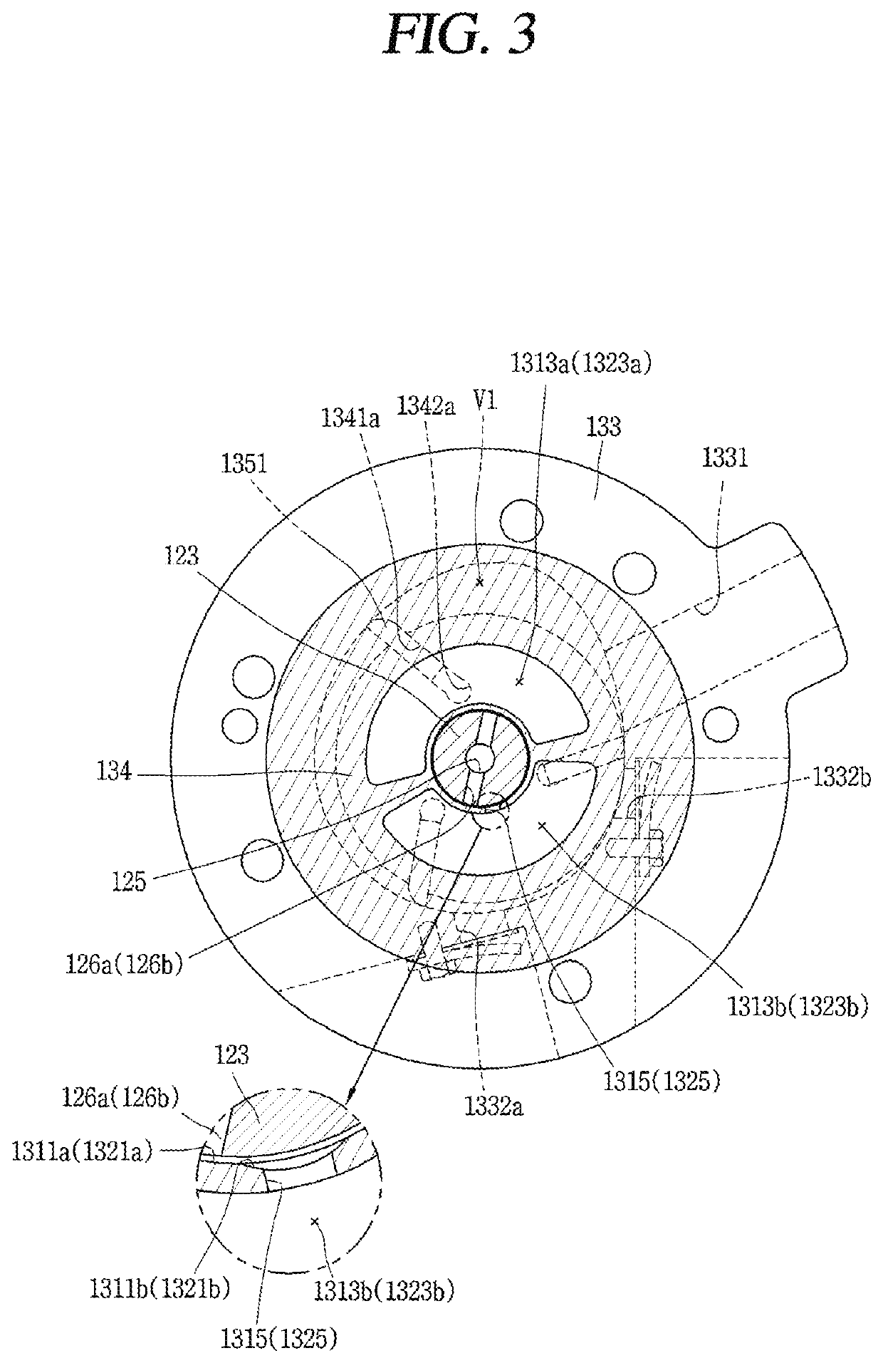
[0055]FIG. 1 is a longitudinal sectional view of an exemplary vane rotary compressor according to the present disclosure, and FIGS. 2 and 3 are horizontal sectional views of a compression unit applied in FIG. 1. FIG. 2 is a sectional view taken along line “IV-IV” of FIG. 1, and FIG. 3 is a sectional view taken along line “V-V” of FIG. 2.

[0056]Referring to FIG. 1, a vane rotary compressor according to the present disclosure includes a driving motor 120 installed in a casing 110 and a compression unit 130 provided at one side of the driving motor 120 and mechanically connected to each other by a rotation shaft 123.

[0057]The casing 110 may be classified as a vertical type or a horizontal type according to a compressor installation method. As for the vertical-type casing, the driving motor and the compression unit are ...


PUM


Abstract

A vane rotary compressor includes a roller rotatably supported in a cylinder and including a plurality of vane slots formed along a circumferential direction with back pressure chambers formed at one end of each of the vane slots A plurality of vanes are slidably supported in the vane slots protruding toward an inner circumferential surface of the cylinder. A compression space formed by the vanes between the roller and the cylinder includes an inlet port and an outlet port formed at both sides of a contact point between the roller and the cylinder. A vane positioned between the inlet port and the outlet port is configured such that a front gap between a front surface of the vane and the inner circumferential surface of the cylinder is smaller than a rear gap between a rear surface of the vane and an inner surface of the back pressure chamber.

Description

CROSS-REFERENCE TO RELATED APPLICATION[0001]Pursuant to 35 U.S.C. § 119(a), this application claims the benefit of earlier filing date and right of priority to Korean Application No. 10-2018-0142076, filed on Nov. 16, 2018, the content of which is incorporated by reference herein in its entirety.BACKGROUND OF THE DISCLOSURE1. Field of the Disclosure[0002]The present disclosure relates to a compressor, more particularly, a vane rotary compressor in which a vane protruding from a rotating roller comes in contact with an inner circumferential surface of a cylinder to form a compression chamber.2. Background Art[0003]A rotary compressor can be divided into two types, namely, a type in which a vane is slidably inserted into a cylinder to come in contact with a roller, and another type in which a vane is slidably inserted into a roller to come in contact with a cylinder. Normally, the former is referred to as a ‘rotary compressor’ and the latter is referred to as a ‘vane rotary compressor...

Claims


Application Information

Patent Timeline
Patent Type & Authority Applications(United States)
IPC IPC(8): F04C18/344
CPCF04C2240/50F04C18/344F04C2210/26F04C18/3445F04C29/00F04C23/008F01C21/0845F01C21/0863F04C2230/602F04C29/023F04C29/128F04C29/06
Inventor PARK, JOONHONGNOH, KIYOULMOON, SEOKHWAN
Owner LG ELECTRONICS INC
Why Eureka
Try Eureka