
Refrigerant compressor, piston of a refrigerant compressor and piston arrangement

a refrigerant compressor and piston technology, applied in the direction of pump components, positive displacement liquid engines, liquid fuel engine components, etc., can solve the problems of reducing the risk of piston deformation during bolt insertion, and the risk of bolt loss substantially smaller, so as to reduce the bolt mass, prevent leakage, and improve sealing

Inactive Publication Date: 2010-02-11
DANFOSS COMPRESSORS +1
View PDF9 Cites 0 Cited by
  • Summary
  • Abstract
  • Description
  • Claims
  • Application Information

AI Technical Summary

Benefits of technology

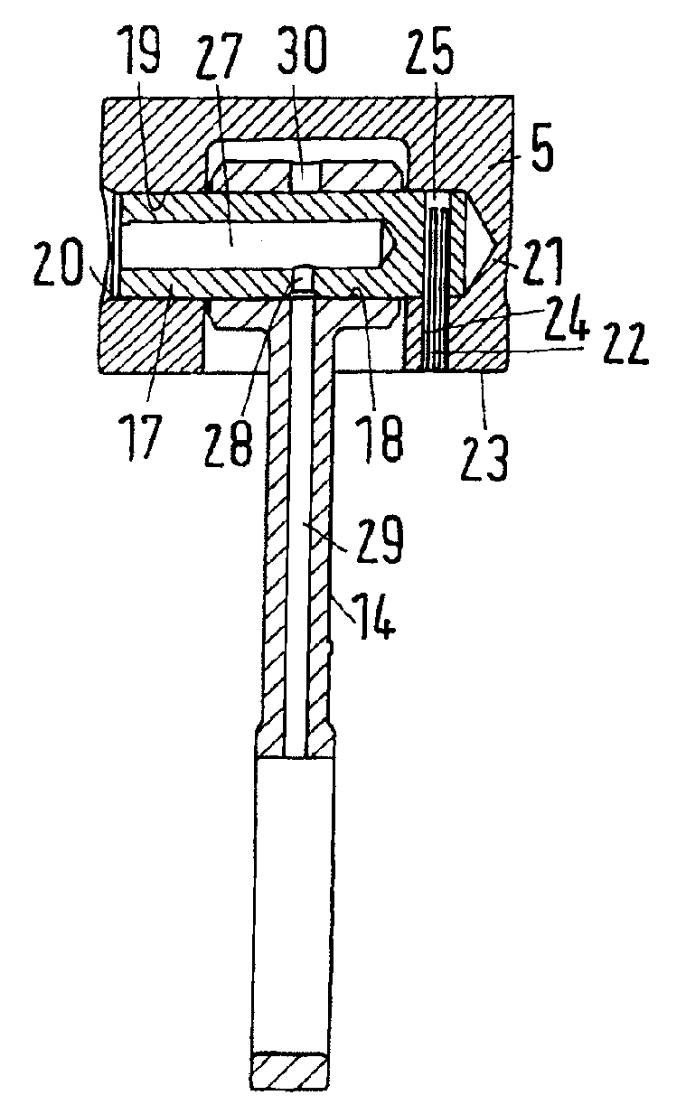
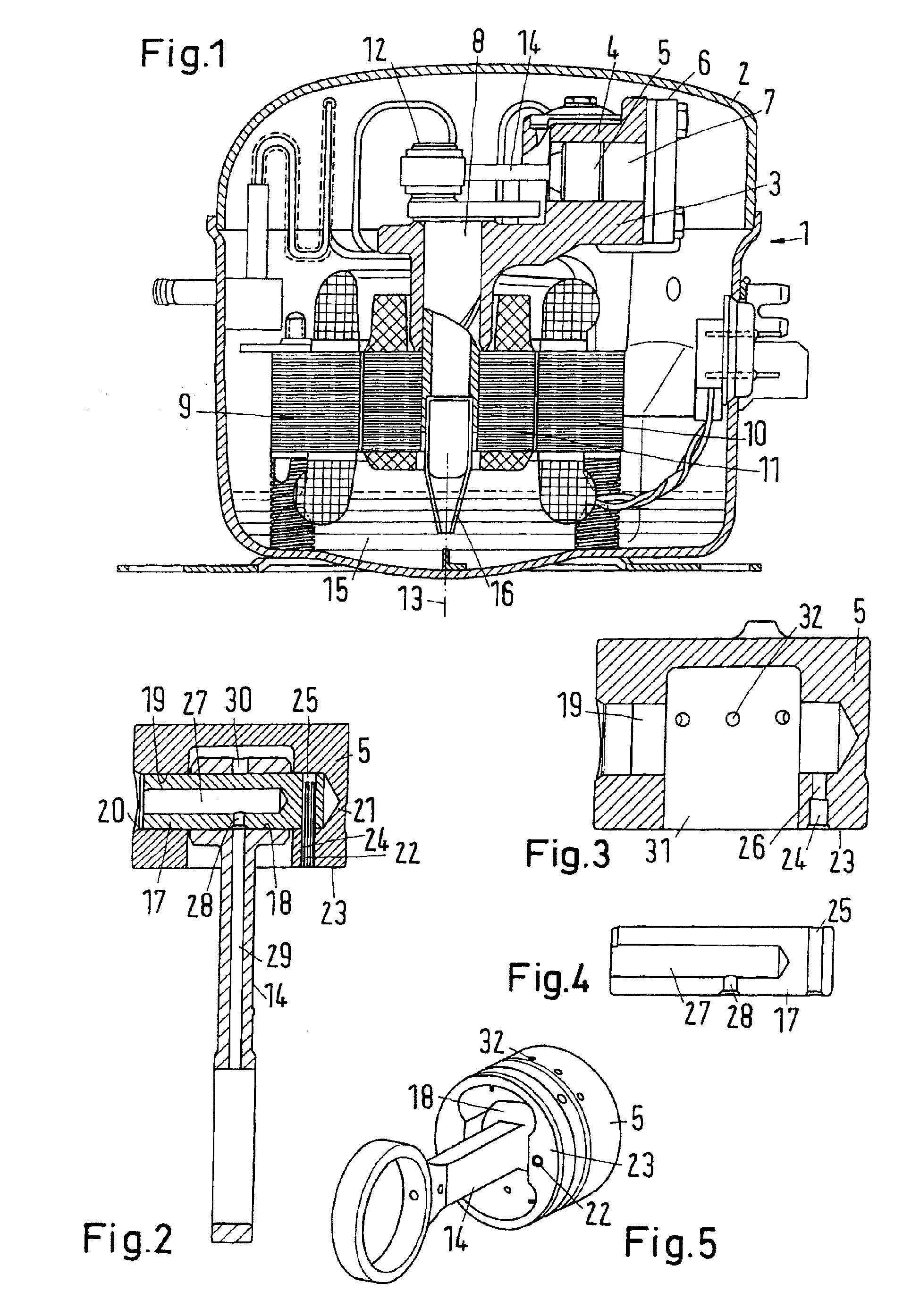
[0008]By means of this design, the leakage of the refrigerant gas is reduced. Contrary to an embodiment, in which the piston is provided with a through-bore, in which the bolt is inserted, the present solution only has one single “weakened area”, through which an increased gas flow can flow, namely in the area of the opening of the blind bore. Due to the reduced leakage, also the noise level is reduced. Accordingly, a muffler can be used, which has a somewhat smaller muffling effect, however, also an accordingly smaller throttle resistance. Also this has a positive effect on the efficiency. Further, with a blind bore, the circumferential wall of the piston only comprises one opening that has to be processed. This means that only in the area of one opening it must be ensured that no burrs or other residuals from a drilling process or the like remain, which could increase the friction between the piston and the cylinder.
[0019]Such a piston has a reduced number of positions, at which the risk of a leakage exists.

Problems solved by technology

With a slide fit, the risk that the piston is deformed during insertion of the bolt is smaller than with a press fit.
As the bolt is inserted in a blind bore, the risk that the bolt is lost is substantially smaller.

Method used


Image

  • Refrigerant compressor, piston of a refrigerant compressor and piston arrangement
  • Refrigerant compressor, piston of a refrigerant compressor and piston arrangement

Examples


Embodiment Construction

[0027]A refrigerant compressor 1 shown in a schematic view in FIG. 1 comprises a hermetically closed housing 2 in the form of a case. In the housing 2 is arranged a compressor block 3 with a cylinder 4, in which a piston 5 is reciprocating. Together with the cylinder 4 and a cylinder head 5, the piston 5 borders a compression chamber 7.

[0028]The movement of the piston 5 in the cylinder 4 is generated by means of a crankshaft 8 that is driven by an electric motor 9. The electric motor 9 has a stator 10 and a rotor 11, to which the crankshaft 8 is connected.

[0029]At one end, the crankshaft 8 is provided with a crank pin 12, which performs an orbiting movement around an axis 13 during operation. A connecting rod 14 is connected to the crank pin 12, the connecting rod 14 being connected to the piston, as will be explained in detail in connection with FIG. 2.

[0030]In the bottom area the housing 2 has an oil sump 15, in which an oil pump 16 is submerged that pumps oil upward through the h...


PUM


Abstract

The invention concerns a refrigerant compressor with a cylinder, in which is arranged a piston (5) that is connected to a crankshaft via a connecting rod (14), the connecting rod (14) having a piston eye (18), through which a bolt (17) inserted in the piston (5) is guided. With such a refrigerant compressor, it is endeavoured to achieve a good efficiency. For this purpose, the bolt (17) is inserted in a blind bore (19).

Description

CROSS REFERENCE TO RELATED APPLICATION[0001]Applicant hereby claims foreign priority benefits under U.S.C. §119 from German Patent Application No. 10 2008 036 999.3 filed on Aug. 7, 2008, the contents of which are incorporated by reference herein.FIELD OF THE INVENTION[0002]The invention concerns a refrigerant compressor with a cylinder, in which is arranged a piston that is connected to a crankshaft via a connecting rod, the connecting rod having a piston eye, through which a bolt inserted in the piston is guided. Further, the invention concerns a piston of such a refrigerant compressor and a piston arrangement with a connecting rod, a bolt and a piston.BACKGROUND OF THE INVENTION[0003]A refrigerant compressor as mentioned in the introduction is, for example, known from DE 195 22 210 C1. Here the bolt is connected to the piston by means of a press fit. In order to reduce a too heavy deformation of the piston, the press fit has a pair of fit surfaces, which are exposed to a reduced ...

Claims


Application Information

Patent Timeline
IPC IPC(8): F04B39/00
CPCF04B53/144F04B39/0022
Inventor ANDERSEN, BRIAN H.SVENDSEN, MORTENBJERRE, PREBENNISSEN, JENS ERIKDAMM-HINRICHSEN, MARTINSCHMIDT, SONKEREINHOLD, SONKEMICHELSEN, SOREN
Owner DANFOSS COMPRESSORS
Learn More