Scroll compressor

a compressor and compressor technology, applied in the direction of machines/engines, rotary/oscillating piston pump components, liquid fuel engines, etc., can solve the problems of difficult adjustment of pushing force, achieve easy reliably sealing, reduce refrigerant leakage loss, and high efficiency operation

Active Publication Date: 2020-11-24
DAIKIN IND LTD
View PDF10 Cites 0 Cited by
  • Summary
  • Abstract
  • Description
  • Claims
  • Application Information

AI Technical Summary

Benefits of technology

[0007]It is an objective of the present invention to provide a low-pressure dome-type scroll compressor in which it is easy to optimally adjust pushing force between a fixed scroll and a movable scroll and which can realize high-efficiency operations in a wide range of operating conditions.
[0022]In the scroll compressor pertaining to the present invention, the floating member pushes the movable scroll against the fixed scroll to reduce refrigerant leakage loss from the tips of the spirals of the scrolls. Additionally, in the scroll compressor pertaining to this invention, the back-pressure space that generates force that pushes the floating member toward the movable scroll is partitioned into the first chamber and the second chamber to which refrigerant in different stages of compression (normally refrigerant at different pressures) is guided. For that reason, it is easy to appropriately adjust the force with which the movable scroll is pushed against the fixed scroll, and high-efficiency operations can be realized in a wide range of operating conditions.

Problems solved by technology

However, in a case where the pressure in a single space (the fluid passageway) is utilized to push the fixed scroll and the movable scroll against each other as in the scroll compressor of JP-A No. 2013-167215, there are cases where it is difficult to adjust the pushing force.
However, in some operating conditions, there are cases where these pressures reverse so that the pressure in the first chamber becomes higher than the pressure in the second chamber.

Method used


Image

  • Scroll compressor
  • Scroll compressor
  • Scroll compressor

Examples


example modification b

(5-2) Example Modification B

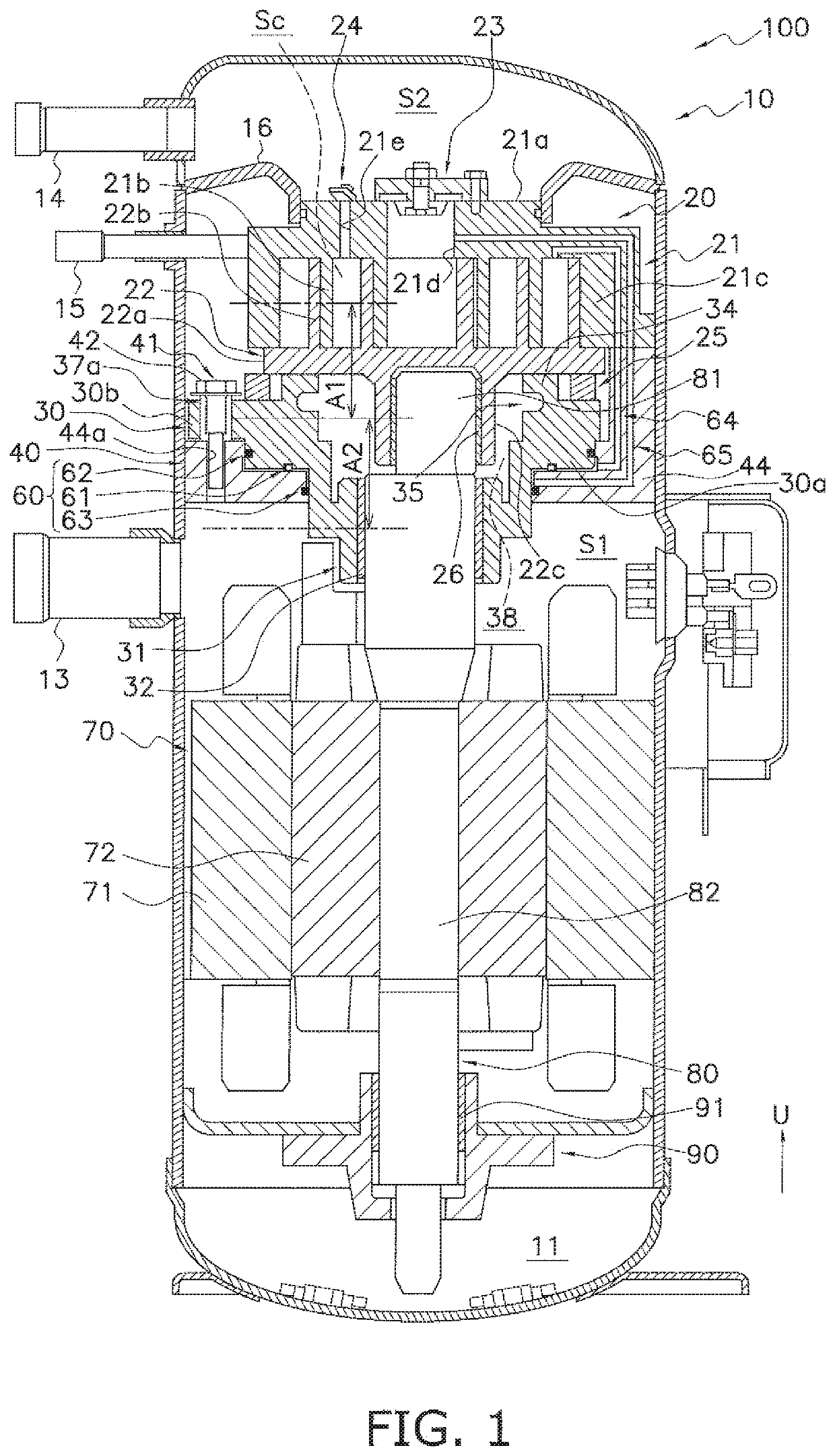
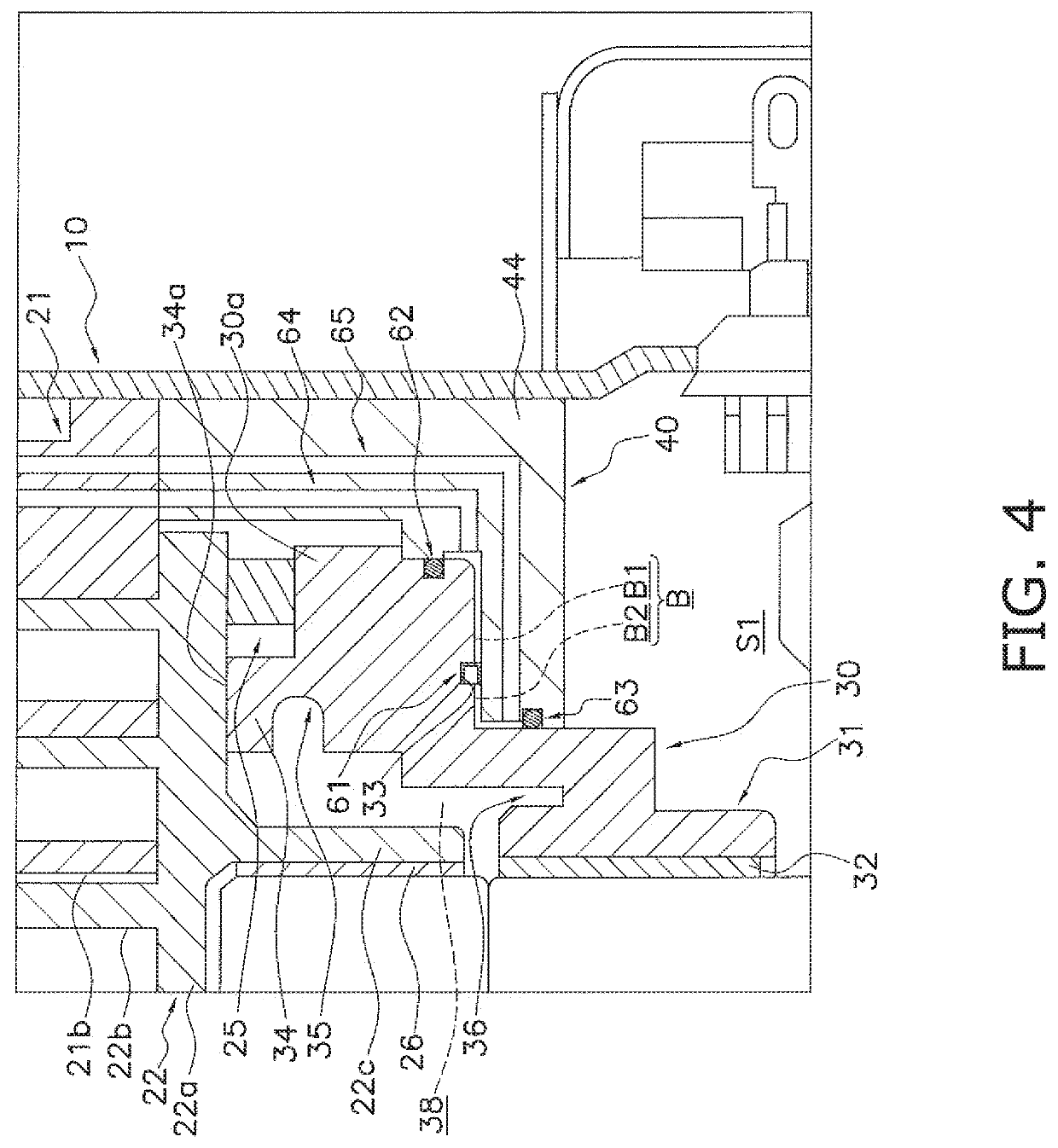
[0123]In the scroll compressor 100 of the above embodiment, the first chamber B1 is disposed on the outer side of the second chamber B2, but the scroll compressor 100 is not limited to this. The second chamber B2 may be disposed on the outer side of the first chamber B1. However, from the standpoint of pushing the movable scroll 22 against the fixed scroll 21 with appropriate force, it is preferred that the second chamber B2 be disposed on the inner side of the first chamber B1.

example modification c

(5-3) Example Modification C

[0124]In the scroll compressor 100 of the above embodiment, as seen in a plan view, the area of the first chamber B1 is greater than the area of the second chamber B2, but the scroll compressor 100 is not limited to this. As seen in a plan view, the area of the second chamber B2 may be greater than the area of the first chamber B1. However, from the standpoint of preventing the force with which the movable scroll 22 is pushed against the fixed scroll 21 from becoming excessive, it is preferred that the area of the first chamber B1 be greater than the area of the second chamber B2.

example modification d

(5-4) Example Modification D

[0125]The scroll compressor 100 of the above embodiment is a vertical scroll compressor in which the drive shaft 80 extends in the vertical direction, but the scroll compressor 100 is not limited to this. The configuration of this invention is also applicable to a horizontal scroll compressor in which the drive shaft of the scroll compressor extends in the horizontal direction.

(5-5) Example Modification E

[0126]In the scroll compressor 100 of the above embodiment, the second seal member 62 and the third seal member 63 are O-rings, but they are not limited to this. For example, instead of O-rings, annular gaskets with U-shaped cross sections that are the same as the one used for the first seal member 61 may be used for the second seal member 62 and the third seal member 63. In this case, the second seal member 62 and the third seal member 63 may be accommodated in accommodation grooves formed in the surface of the floating member 30 or the housing 40 that i...


PUM


Abstract

A scroll compressor includes a compression mechanism having fixed and movable scrolls forming a compression chamber, a motor to drive the movable scroll, a casing accommodating the compression mechanism and the motor, a housing accommodated inside the casing, a floating member supported by the housing, a first seal member, and first and second flow passages. An inside of the casing is partitioned into first and second spaces. The floater member can be pushed toward the movable scroll by pressure in a back-pressure space formed between the floating member and the housing. The first seal partitions the back-pressure space into first and second chambers. The first flow passage guides the refrigerant in the middle of compression in the compression mechanism to the first chamber. The second guides the refrigerant discharged from the compression mechanism to the second chamber.

Description

CROSS-REFERENCE TO RELATED APPLICATIONS[0001]This U.S. National stage application claims priority under 33 U.S.C. § 119(a) to Japanese Patent Application No. 2016-169770, filed in Japan on Aug. 31, 2016, the entire contents of which are hereby incorporated herein by reference.TECHNICAL FIELD[0002]The present invention relates to a scroll compressor. More specifically, the present invention relates to what is called a low-pressure dome-type scroll compressor divided into a high-pressure space to which refrigerant is discharged from a compression mechanism and a low-pressure space in which a motor that drives the compression mechanism is disposed.BACKGROUND ART[0003]Conventionally, scroll compressors which are called as low-pressure dome-type scroll compressors have been known as in JP A No. 2013-167215. In the low-pressure dome-type scroll compressor, the inside of a casing is divided into a high-pressure space to which refrigerant is discharged from a scroll compression mechanism an...

Claims


Application Information

Patent Timeline
Patent Type & Authority Patents(United States)
IPC IPC(8): F04C18/02F04C29/00F04C27/00F04C23/00
CPCF04C27/005F04C18/0261F04C27/008F04C18/02F04C23/008F04C18/0246F04C29/0021F04C18/0215F04C2240/30F04C2240/60F05B2210/14
Inventor YOSUKE, YOSHINOBUZHAO, YONGSHENG
Owner DAIKIN IND LTD
Why Eureka
Try Eureka