Rotor Structure of Screw Compressor and Inverter Screw Compressor With Same

a compressor and screw technology, applied in the field of compressors, can solve the problems of reducing the compression performance of the inverter compressor, the narrow application range of the constant frequency screw compressor, and the limited compression performance of the screw compressor, so as to reduce the leakage of refrigerant inside the rotor structure, the configuration of the tooth profile is more reasonable, and the effect of effective optimization of the tooth profil

Active Publication Date: 2021-09-09
GREE ELECTRIC APPLIANCES INC
View PDF2 Cites 0 Cited by
  • Summary
  • Abstract
  • Description
  • Claims
  • Application Information

AI Technical Summary

Benefits of technology

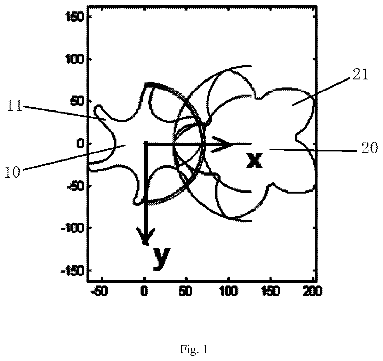
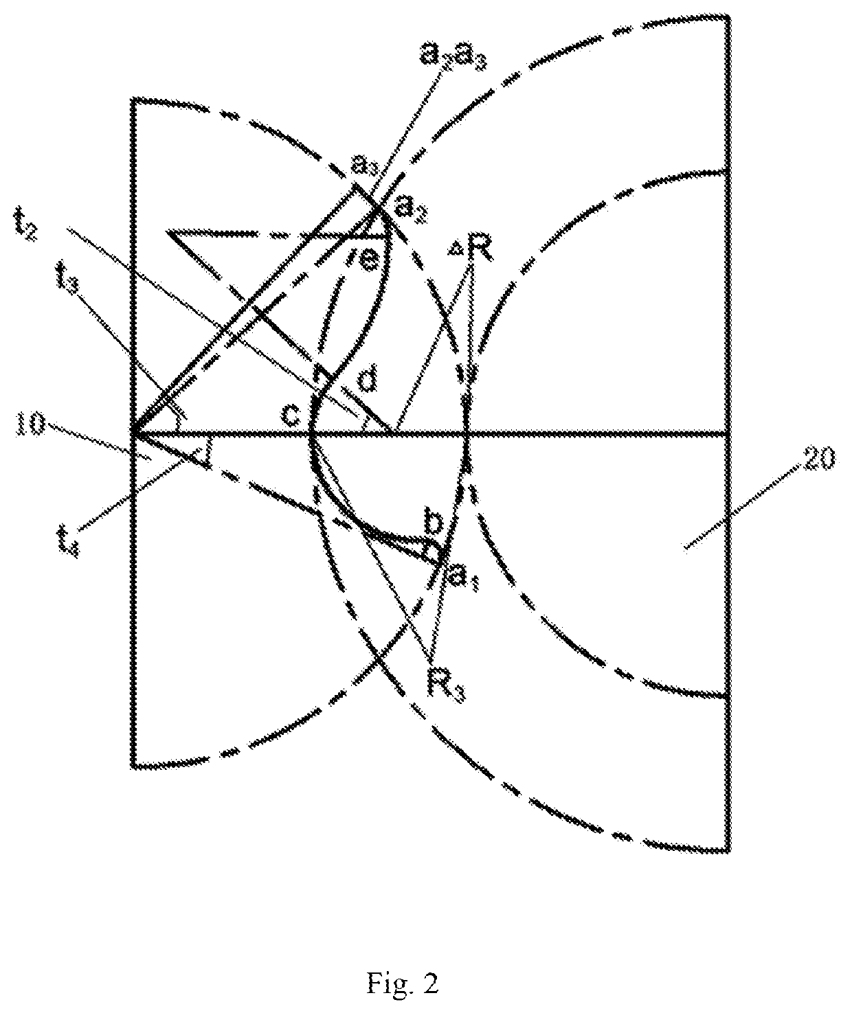
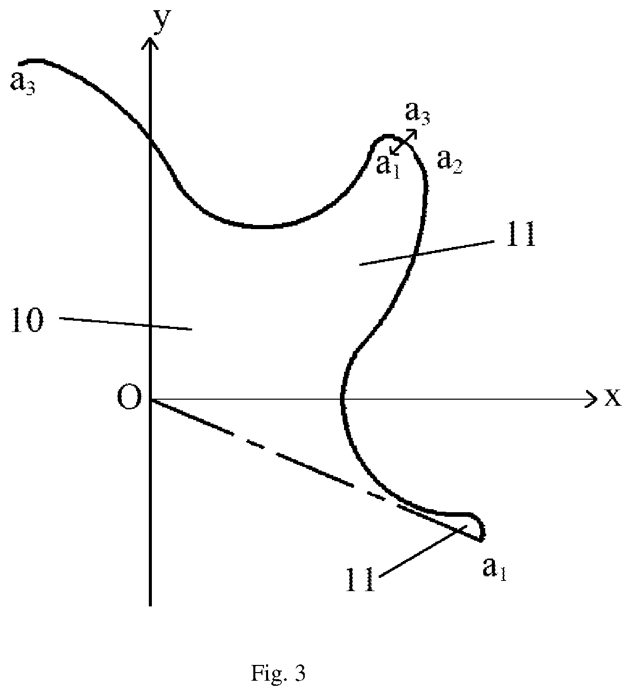
[0017]By applying the technical solution of the present disclosure, the tooth profile is formed between tooth crests of two adjacent female teeth on an end surface of the female rotor body, and the tooth profile is formed by sequentially connecting an arc segment a1b, an envelope bc, an arc segment cd, an arc segment de, an arc segment ea2, an arc segment a2a3 in an end-to-end fashion along a counterclockwise direction, wherein centers of the arc segment cd and the arc segment de are located on both sides of the tooth profile. Such arrangement is adapt to effectively optimize the tooth profile, so that the opening of the tooth profile is larger than that of the tooth profile of the rotor structure in the related art, then a variation of pressure difference between an internal environment and an external environment of the rotor structure is reduced, thereby a leakage of refrigerant from inside the rotor structure is reduced. The rotor structure is adopted to make a configuration of the tooth profile more reasonable and reduce a rotation speed of the rotor structure at the same flow rate. In particular, an inverter screw compressor with the rotor structure is adapted to make a profile of the rotor structure suitable for the inverter screw compressor, then a leakage of the compressor is effectively reduced, thereby a compression energy efficiency and application of the inverter screw compressor is improved.

Problems solved by technology

In a related art, a constant frequency screw compressor has a limited compression performance, which causes a problem of a narrow application range for the constant frequency screw compressor.
However, in contrast with the inverter compressor, since a rotation speed of the inverter compressor is variable so that if a profile of a rotor teeth of the constant frequency screw compressor is directly used, it is likely to cause a problem of a reduced compression performance of the inverter compressor.
Furthermore, a problem of a substantial refrigerant leakage during a compression process of the compressor is caused due to the unreasonable profile configuration of the rotor structure of the constant frequency screw compressor or the inverter screw compressor in the related art.

Method used


Image

  • Rotor Structure of Screw Compressor and Inverter Screw Compressor With Same
  • Rotor Structure of Screw Compressor and Inverter Screw Compressor With Same
  • Rotor Structure of Screw Compressor and Inverter Screw Compressor With Same

Examples


Embodiment Construction

[0024]It should be noted that the embodiments in the present disclosure and the features in the embodiments may be combined with each other in the case where there is no conflict. The present disclosure will be described in detail below with reference to the accompanying drawings and in conjunction with the embodiments.

[0025]It should be noted that the terms used here are only for describing specific embodiments, not intended to limit exemplary embodiments according to the present disclosure. As used here, unless explicitly indicated otherwise in the context, the singular form is also intended to include the plural form. In addition, it should also be understood that when the terms “comprising” and / or “including” are used in the present specification, it is indicated that there are features, steps, operations, devices, assemblies, and / or combinations thereof.

[0026]It should be noted that the terms “first”, “second” and the like in the specification, claims and accompanying drawings ...


PUM


Abstract

Provided is a rotor structure of a screw compressor and an inverter screw compressor with the same. The rotor structure includes: a female rotor including a female rotor body, wherein the female rotor body is includes a plurality of female teeth, and a tooth profile is formed between tooth crests of two adjacent female teeth of the female rotor body, and the tooth profile is formed by sequentially connecting an arc segment a1b, an envelope bc, an arc segment cd, an arc segment de, an arc segment ea2, an arc segment a2a3 from front to rear along a counterclockwise direction, wherein centers of the arc segment cd and the arc segment de are respectively located on both sides of the tooth profile. The tooth profile reduces rotation speed of the rotor structure. The inverter screw compressor reduces the leakage of the compressor and improves the compression energy efficiency and application of the compressor.

Description

CROSS-REFERENCE TO RELATED APPLICATIONS[0001]This application is the United States national phase of International Application No. PCT / CN2018 / 120371 filed Dec. 11, 2018, and claims priority to Chinese Patent Application No. 201810130545.2 filed Feb. 8, 2018, the disclosures of which are hereby incorporated by reference in their entirety.BACKGROUND OF THE INVENTIONField of the Invention[0002]The present disclosure relates to the technical field of a compressor device, in particular to a rotor structure of a screw compressor and an inverter screw compressor with the same.Description of Related Art[0003]In a related art, a constant frequency screw compressor has a limited compression performance, which causes a problem of a narrow application range for the constant frequency screw compressor. For the constant frequency screw compressor, there is already a set of optimized profile. However, in contrast with the inverter compressor, since a rotation speed of the inverter compressor is va...

Claims


Application Information

Patent Timeline
Patent Type & Authority Applications(United States)
IPC IPC(8): F04C18/16F04C18/08
CPCF04C18/16F04C2240/20F04C2250/20F04C18/084
Inventor LIU, HUAZHANG, TIANYILI, RIHUALONG, ZHONGKENGXU, YUNGONG
Owner GREE ELECTRIC APPLIANCES INC
Why Eureka
Try Eureka