Scroll compressor for a vehicle air-conditioning system having spiral wall including conical cut

a technology of spiral wall and compressor, which is applied in the direction of machines/engines, manufacturing tools, liquid fuel engines, etc., can solve the problems of increased torque and compressive force, redundancy of the contact system, and significant decrease of the wall thickness at the end segment, so as to improve the leak-tightness of the outer, reduce the overpressure, and reduce the effect of wear and tear

Active Publication Date: 2021-04-27
HANON SYST
View PDF17 Cites 0 Cited by
  • Summary
  • Abstract
  • Description
  • Claims
  • Application Information

AI Technical Summary

Benefits of technology

[0014]According to the concept, in the spiral end region, i.e. in the proximity of the inner end of at least one of the spirals, the stationary and / or the orbiting spiral, a conical cut is developed. The conical cut connects the inner compression chamber, formed by the opposing spiral regions of the stationary and the orbiting spiral, more easily with the main refrigerant outlet port than would be the case without the cut at the end of the spiral. This supports the gas in being enabled to flow out of the main refrigerant outlet port precisely at the point at which the compression chamber reaches ejection pressure such that no generation of undesirable overpressure can occur. The conical cut leads to the condition that in a certain rotational drive angle range of the compressor no contact exists between the two spirals. This improves the leak-tightness of the outer low pressure chambers. In addition, contact forces between the spirals are thereby gradually shifted to the outer windings where the curvature is lesser and the radius greater. This reduces the wear and tear considerably.
[0015]The conical development of the cut consequently leads to a decrease of the overpressure at the end of the compression and to an improvement in the sealing of the compression chambers with a noticeable reduction of leakage of the refrigerant. At the operating points at which such is necessary, the overpressure can be decreased without losing too much volumetric efficiency. An enhancement of the isentropic efficiency is thereby achieved.
[0016]According to an advantageous embodiment of the invention, the conically shaped cut extends over the entire height of the spiral wall, i.e. from the upper end to the lower end of the spiral wall. The volume of the cut is herein distributed from the upper end to the lower end of the spiral wall corresponding to the oblique shape. The conical shape brings about a smooth characteristic of the cross sectional course with which the connection of two pressure chambers is released. Due to the conical shape of the cut an oblique edge is preferably obtained that extends over the entire height of the spiral wall and improves the transition of the different contact points between the spiral walls. It is especially advantageous if the cut is implemented in such manner and the oblique edge is inclined at such angle that the thickness of the spiral wall at its lower end in the proximity of the cut is the same as in the regions of the spiral outside of the cut, i.e. that the wall thickness at the lower end of the spiral is maintained. The mechanical strength, rigidity and loading resistance of the spiral in the spiral end region is not negatively affected. Since the cut extends over the entire height from the upper to the lower end of the spiral, in the generation of the conical cut, less material has to be cut away in the longitudinal direction of the spiral at a volume that is unchanged compared to a prismatic cut according prior art.

Problems solved by technology

The disadvantages of the known prior art reside therein that in the region of the cut there is contact between the fixed and the moving spiral body.
This leads to redundancy of the contact system.
The strain on the thinnest segment of the wall causes deformations of the wall, which can lead directly to a fracture or it can augment the problems caused by the contact of the two spirals, such as for example increased temperature, wear and friction.
A further difficulty caused by corresponding designs of prior art is the significant decrease of the wall thickness at the end segment and a reduction entailed therein of the size of the end area for discharging the small volumes of the refrigerant after the compression.
The suboptimal refrigerant flow in the direction toward the refrigerant outlet port of the scroll compressor, which is caused by the currently used geometry of the cut at the end region of at least one of the spirals, represents a further problem since a less optimal refrigerant flow leads to an increased torque and increased compressive force (overpressure) on the wall of the cut in the end region and therein to an unbalanced forces / torque system in the middle of the spiral.

Method used


Image

  • Scroll compressor for a vehicle air-conditioning system having spiral wall including conical cut
  • Scroll compressor for a vehicle air-conditioning system having spiral wall including conical cut
  • Scroll compressor for a vehicle air-conditioning system having spiral wall including conical cut

Examples


Embodiment Construction

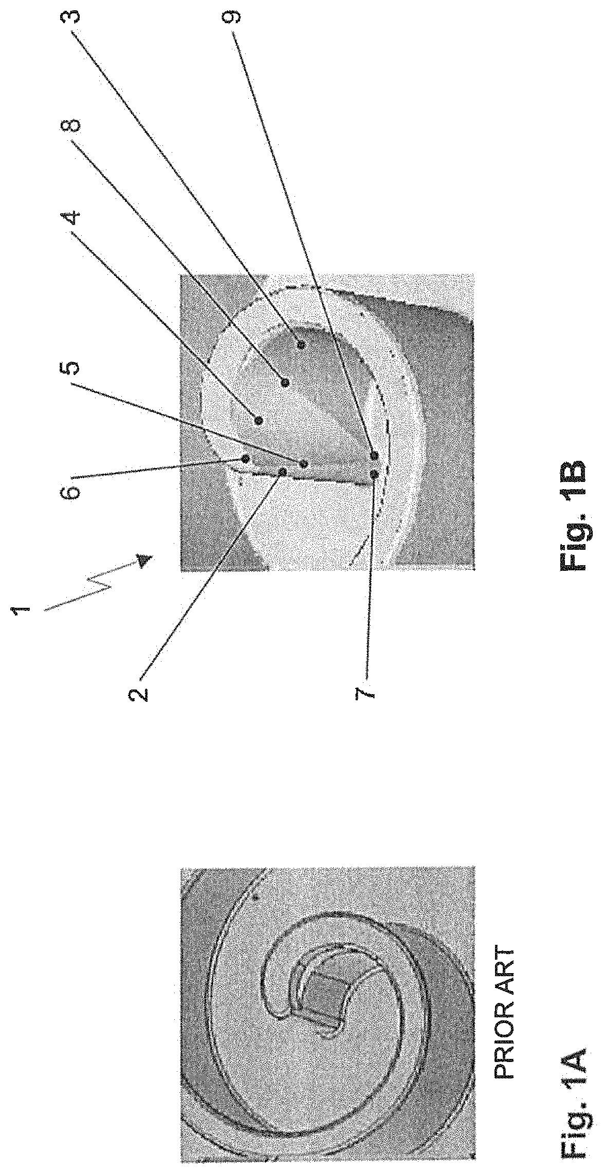
[0029]FIG. 1A shows a spiral of a scroll compressor with a prismatically cut form of the spiral end region according to prior art. In its spiral end region the depicted spiral comprises a vertical cut denoted as prismatic. The wall thickness in the spiral end region is significantly less than in the region of the remaining spiral.

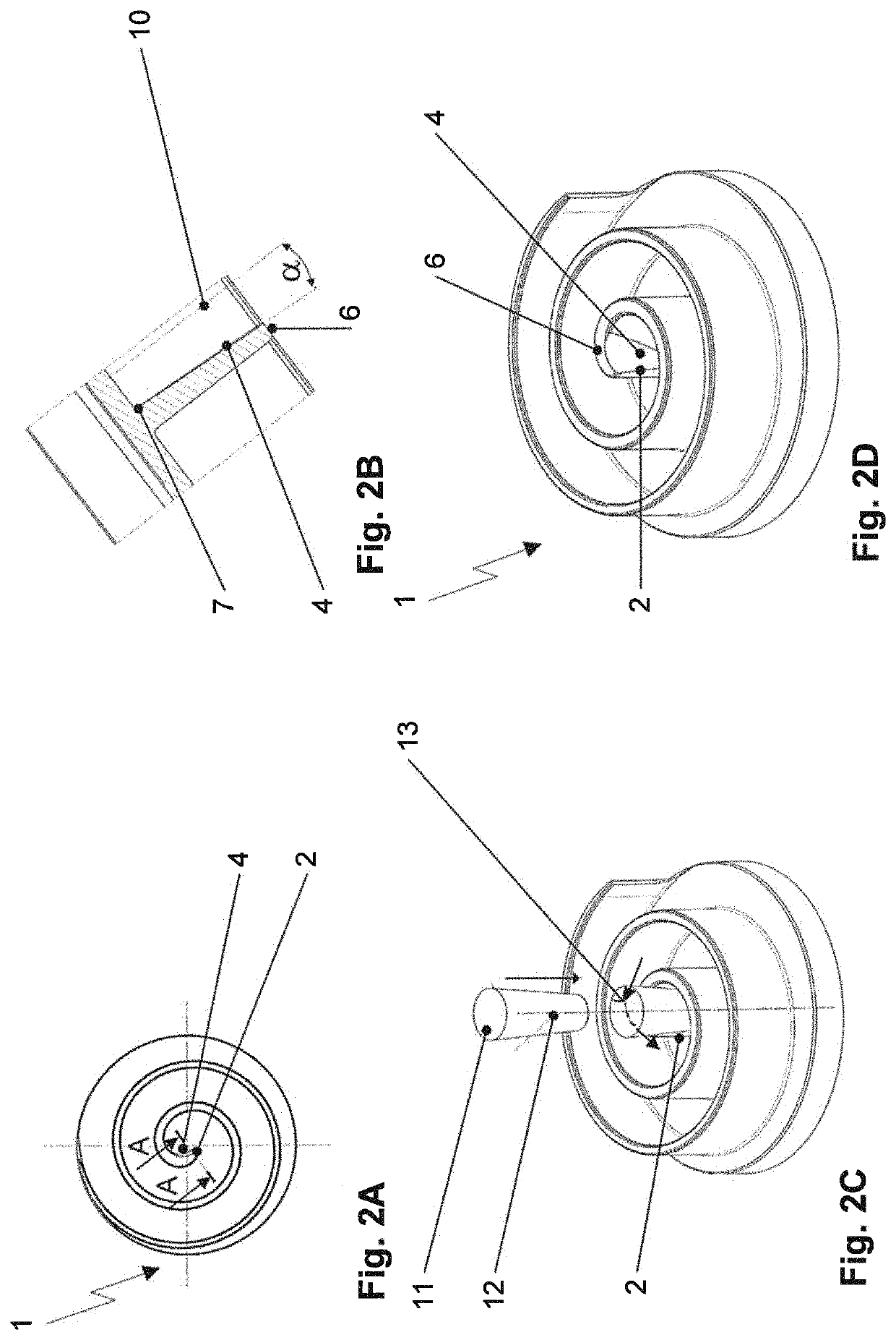
[0030]FIG. 1B shows an embodiment example according to the invention of a spiral 1 of a scroll compressor, stated more precisely of its spiral end region. In the spiral end region at the inner end 2 of spiral 1 the concave side 3 of the spiral wall is provided with a cut 4 which has the generated shell form of a concavely curved surface of a cone segment. Through the conical form of the cut 4 an oblique edge 5 results on the inner end 2 of spiral 1, wherein the oblique edge 5 extends over the entire height of the spiral wall. Consequently, the volume of the cut 4, in accordance with its oblique shape, is distributed from its upper end 6 to the lower end 7 o...


PUM


Abstract

A scroll compressor for a motor vehicle air-conditioning system includes a compressor housing, two interleaving spirals within the compressor housing, of which one spiral is stationary and the other spiral is movable eccentrically on a circular orbit, whereby the volume of compression chambers formed between the spirals changes cyclically and refrigerant is suctioned in and compressed; at least one refrigerant outlet port for ejecting the compressed refrigerant in a wall, frontal to the spirals, of the compressor housing in the center of the stationary spiral, wherein in the spiral end region on the inner end of at least one of the two spirals the concave side of the spiral wall is provided with a cut that has the form of a cone segment with concave curvature, decreasing from the upper end in the direction toward the lower end of the spiral wall.

Description

CROSS REFERENCE TO RELATED APPLICATIONS[0001]This application claims priority from German Patent Application No. 102017110759.2 filed May 17, 2017, which is hereby incorporated by reference in its entirety.FIELD OF THE INVENTION[0002]The invention relates to a scroll compressor for a motor vehicle air-conditioning system, comprising two interleaving spirals one of which having a truncation cut at its inner end.BACKGROUND OF THE INVENTION[0003]The term scroll compressor is the customary technical term for a compressor type that is also known as gear worms compressor or spiral compressor. A scroll compressor operates according to the principle of positive displacement. As a rule, it consists of two interleaving spirals of which one is stationary and the other is moved eccentrically on a circular orbit. The spirals herein maintain minimal spacing from one another and with each orbiting gyration form two increasingly smaller compression chambers. The gas to be pumped is hereby externall...

Claims


Application Information

Patent Timeline
Patent Type & Authority Patents(United States)
IPC IPC(8): F04C18/02
CPCF04C18/0284F04C18/0215F04C18/0269F04C2230/10F04C2250/201F04C29/00F04C2240/10F04C2240/20B23C5/12B23C2210/242B60H1/3223F04C2210/26F05B2210/14F05B2230/10F05B2240/20
Inventor GUNTERMANN, BERNDDURSUN, KADIRARRIAZU, LAURA
Owner HANON SYST
Why Eureka
Try Eureka