Non-circulating coolant PEM fuel cell power plant with antifreeze back pressure air venting system

a fuel cell power plant and back pressure technology, applied in emergency supply, electrical generators, sustainable buildings, etc., can solve the problems of increasing system complexity and cost, forcing the shut down of the system and power plant, etc., and achieve the effect of improving heat rejection from the system

Active Publication Date: 2009-12-31
AUDI AG
View PDF7 Cites 0 Cited by
  • Summary
  • Abstract
  • Description
  • Claims
  • Application Information

AI Technical Summary

Benefits of technology

[0009]The humidified air stream is vented from the fuel cell system to ambient surroundings through a hydrophobic porous body and into and through a passive column of antifreeze which is disposed in proximity with the separator. The air in the vented stream bubbles through the antifreeze into ambient surroundings. Any water in the vented stream also passes through the antifreeze. If so desired, the antifreeze can be one which is immiscible with water whereby the water constituent will rise through the antifreeze and will separate from the antifreeze, and will not dilute the antifreeze. The water layer can then be removed from the antifreeze layer by means of a micro porous membrane. The antifreeze layer will maintain the desired back pressure in the fuel cell system.
[0010]The air stream in the system is pressurized for several reasons. First, operating at higher pressures is expected to improve heat rejection from the system in part by raising the temperature of the air / vapor mix leaving the stack. Secondly, the fuel and air pressures must be higher than the coolant water pressure to prevent water from flooding the porous bodies in the unitized electrode assemblies in the power plant.
[0011]It will be appreciated that the antifreeze air venting component of the system will function properly at freezing and subfreezing temperatures, and is passive in that it does not require any moving parts in contact with freezing water for proper operation.

Problems solved by technology

This fact causes operational problems during freezing conditions since the valves and / or nozzles in the air bleed line can freeze up so that air flow can no longer be properly controlled from the system, thus forcing shut down of the system and of the power plant.
This problem can be fixed by heating the air bleed line but this solution requires additional heating equipment in the system that increases system complexity and cost.

Method used


Image

  • Non-circulating coolant PEM fuel cell power plant with antifreeze back pressure air venting system
  • Non-circulating coolant PEM fuel cell power plant with antifreeze back pressure air venting system

Examples


Embodiment Construction

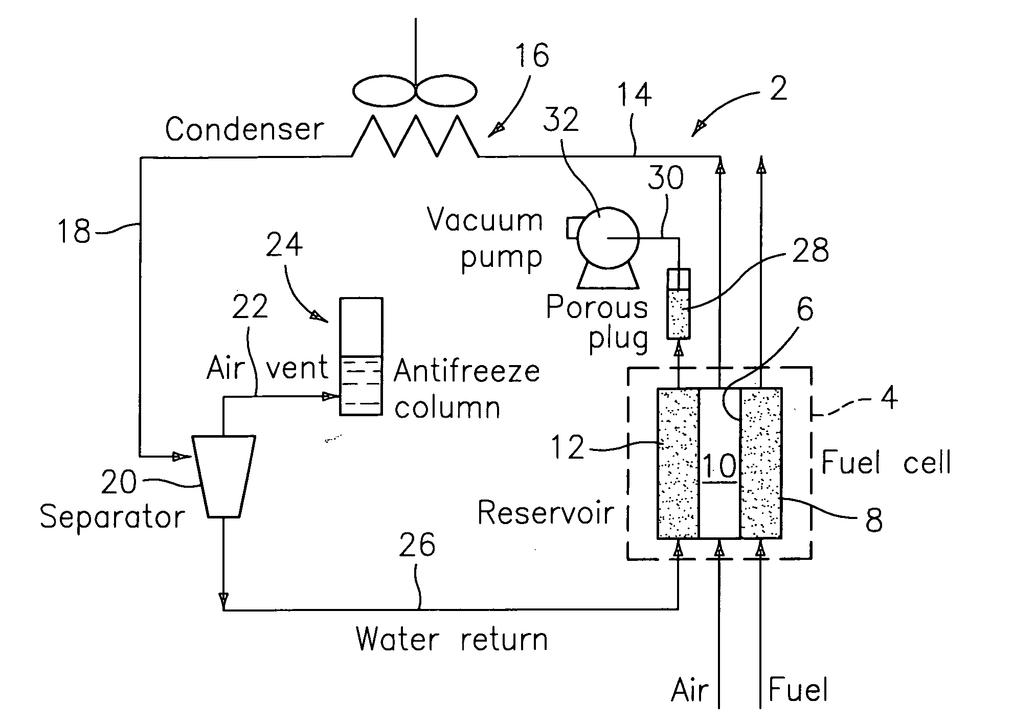
[0015]Referring now to the drawings, FIG. 1 is a schematic view of a PEM cell subassembly part denoted generally by the numeral 2 of a fuel cell power plant formed in accordance with this invention. The fuel cell 4 includes a catalyzed polymer electrolyte membrane 6 which is interposed between a fuel reactant flow field 8 (the anode side) and an oxidant reactant flow field 10 (the cathode side). A coolant flow field 12 is disposed adjacent to the cathode side 10 of the fuel cell 4, however, the coolant flow field 12 could be positioned closer to the anode side 8 of the cell 4. The coolant flow field 12 contains a non-circulating aqueous coolant that serves to cool the PEM cell subassembly 2 so as to maintain the proper operating temperature of the fuel cell 4. During the reaction, the hydrogen in the fuel and the oxygen in the air are converted to electrons and product water. Some of this product water is evaporated from the coolant flow field, in the form of water vapor, into the o...


PUM

PropertyMeasurementUnit
pressuresaaaaaaaaaa
heightaaaaaaaaaa
pressureaaaaaaaaaa

Abstract

A PEM fuel cell (4) power plant includes a passive air vent (24) through which air separated from a cathode effluent stream can be expelled from the power plant. The air vent operates satisfactorily during ambient freezing conditions thus it is eminently suitable for use in mobile applications such as in PEM fuel cell-powered automobiles, buses, or the like. The vent is formed from a liquid antifreeze layer (40) that is disposed in a sparging tank (36) which communicates with ambient surroundings. Any water vapor in the stream can condense out of the gas-stream in the antifreeze. In order to facilitate this result, the antifreeze can be a liquid that is immiscible with water so that the condensed water will form a separate layer (38) in the sparging tank.

Description

[0001]This application claims the benefit of PCT / US 05 / 46913, filed December 23, 2005.TECHNICAL FIELD[0002]The present invention relates to a polymer electrolyte membrane (PEM) fuel cell power plant which is cooled evaporatively by a non-circulating water (NWM) coolant, an NWM PEM fuel cell system. More particularly, this invention relates to a PEM fuel cell power plant which can operate at freezing temperatures. The system has an air-water separator for separating air from water which are contained in the cathode effluent gas stream. Air from the separator is then vented from the system through an antifreeze column and the water is returned to the coolant section of the system.BACKGROUND OF THE INVENTION[0003]Polymer electrolyte membrane fuel cell assemblies are relatively low temperature low operating pressure fuel cell assemblies that utilize a catalyzed polymer membrane electrolyte to process air and a hydrogen-rich fuel to produce electricity and water. PEM fuel cells are well ...

Claims


Application Information

Patent Timeline
Patent Type & Authority Applications(United States)
IPC IPC(8): H01M8/04
CPCH01M8/04029H01M8/04164Y02E60/50H01M2250/10Y02B90/14H01M2008/1095Y02B90/10
Inventor DARLING, ROBERTSKIBA, TOMMY
Owner AUDI AG
Why Eureka
Try Eureka