
System and method for controlling an exhaust brake of a vehicle

a technology of exhaust brake and system, which is applied in the direction of electrical control, machines/engines, valve arrangements, etc., can solve the problems of engine components being damaged, the performance of the conventional exhaust brake is not good, etc., and achieve the effect of preventing damage to the engine components and improving the performance of the conventional exhaust brak

Active Publication Date: 2016-02-09
HYUNDAI MOTOR CO LTD
View PDF13 Cites 0 Cited by
  • Summary
  • Abstract
  • Description
  • Claims
  • Application Information

AI Technical Summary

Benefits of technology

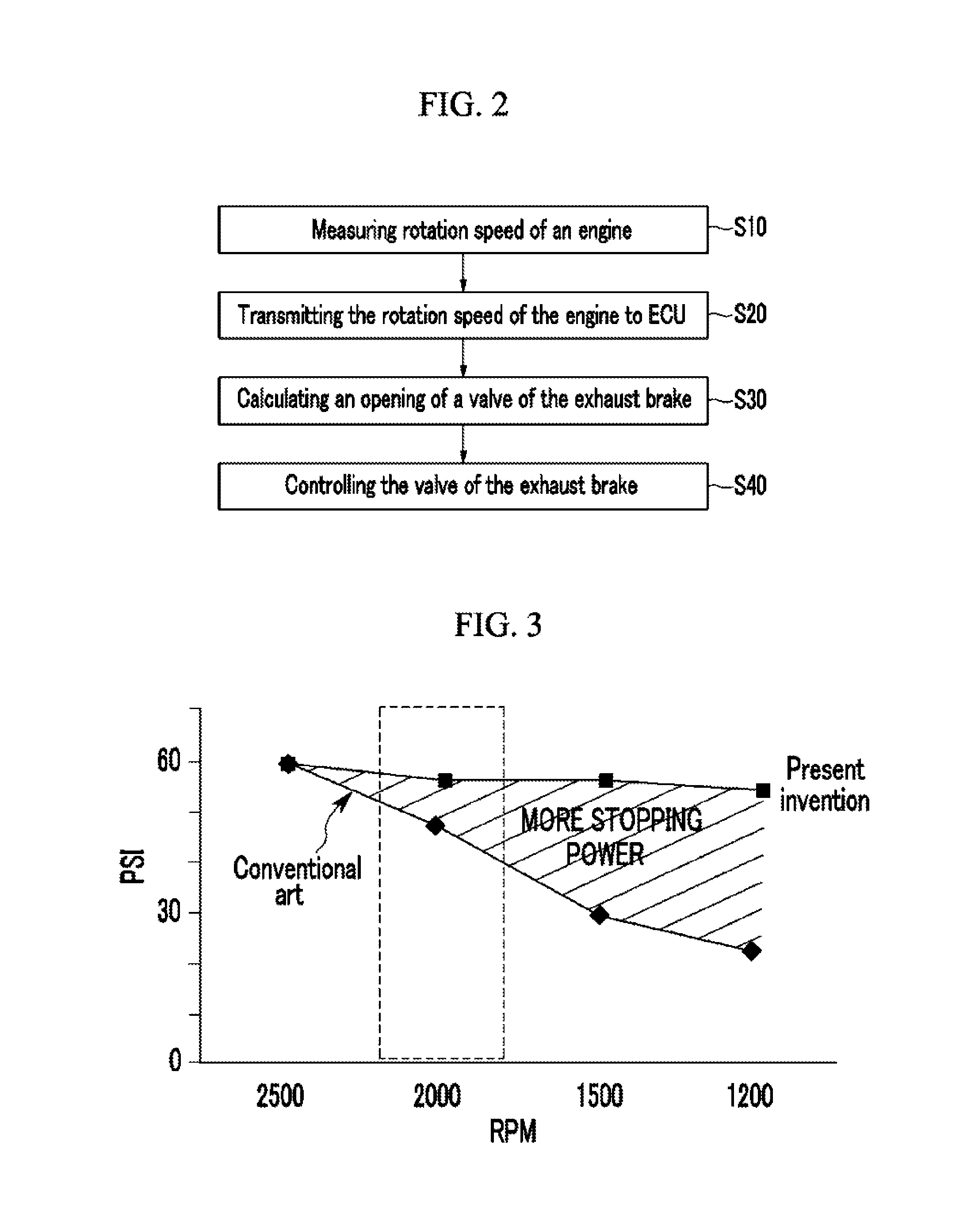
The present invention provides a system and method for controlling an exhaust brake of a vehicle that has two main benefits: improving performance at low and medium engine speeds and preventing damage to engine components. The system works by constantly maintaining back pressure of the exhaust brake at any engine speed. This results in faster and more effective braking at lower engine speeds and prevents damage to the engine components by keeping the back pressure high during higher engine speeds. Overall, the system and method improve the performance and reliability of exhaust brakes in vehicles.

Problems solved by technology

However, the conventional exhaust brake has a problem of performance degradation at low and medium engine speeds such as the main speed of an engine by fixing the valve opening of the exhaust brake so as to maintain the back pressure below the permissible back pressure at a maximum rotation speed of the engine.
The conventional exhaust brake has a further problem that components of the engine can be damaged by excessive back pressure caused by an excessively high engine speed, because the opening of the butterfly valve is constantly maintained even when the engine speed is excessively high.

Method used


Image

  • System and method for controlling an exhaust brake of a vehicle
  • System and method for controlling an exhaust brake of a vehicle
  • System and method for controlling an exhaust brake of a vehicle

Examples


Embodiment Construction

[0029]Reference will now be made in detail to various embodiments of the present invention(s), examples of which are illustrated in the accompanying drawings and described below. While the invention(s) will be described in conjunction with exemplary embodiments, it will be understood that the present description is not intended to limit the invention(s) to those exemplary embodiments. On the contrary, the invention(s) is / are intended to cover not only the exemplary embodiments, but also various alternatives, modifications, equivalents and other embodiments, which may be included within the spirit and scope of the invention as defined by the appended claims.

[0030]An exemplary embodiment of the present invention will hereinafter be described in detail with reference to the accompanying drawings.

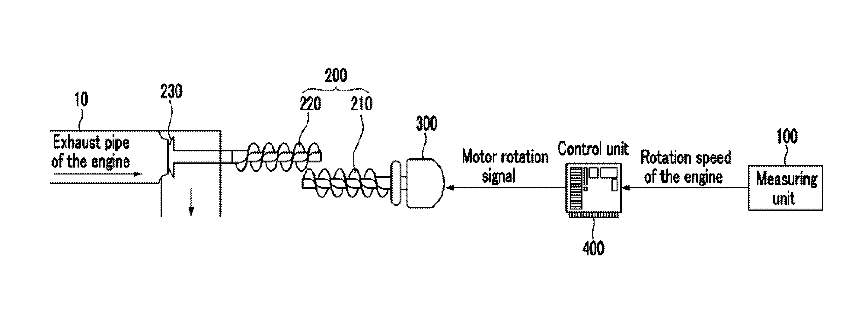
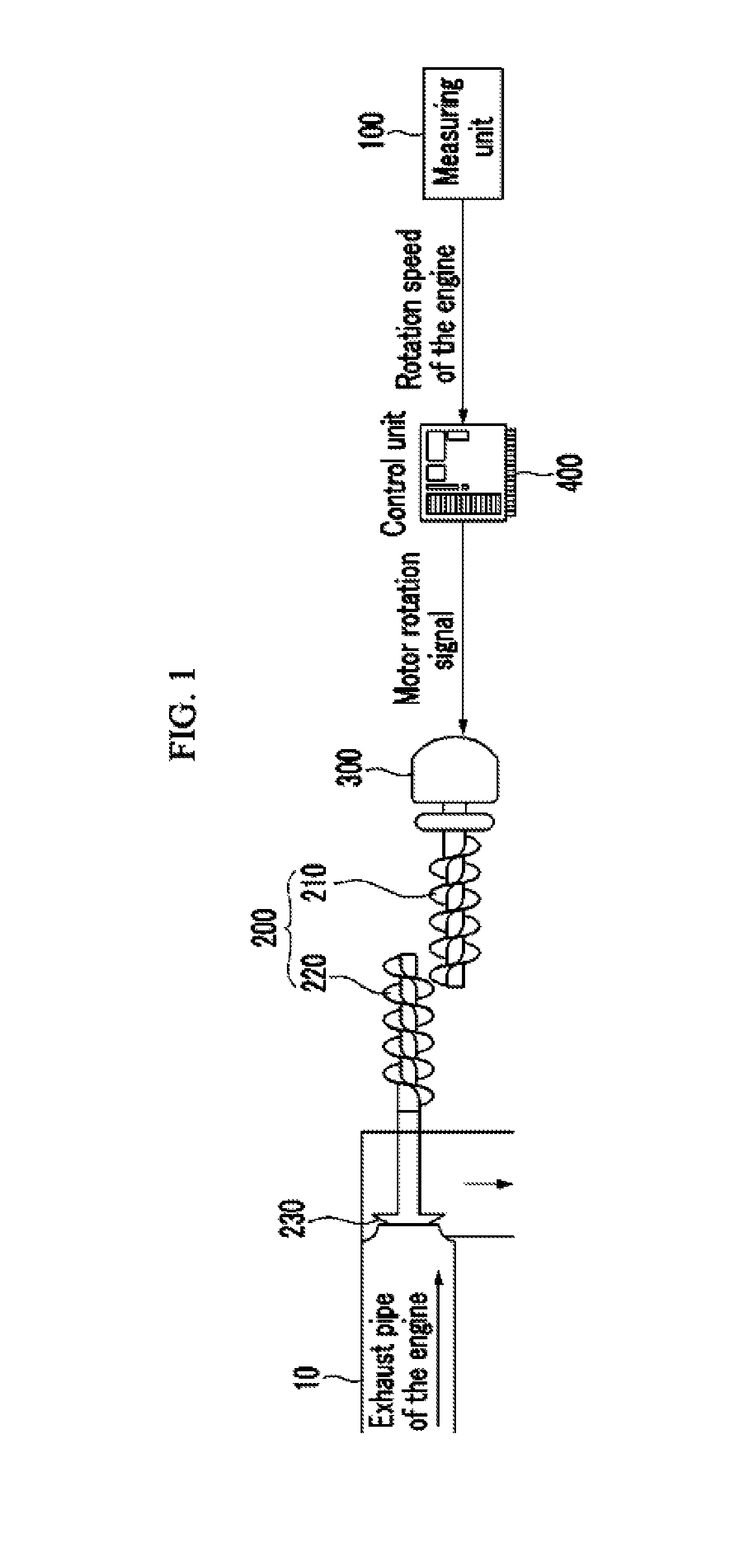
[0031]As shown in FIG. 1, a system for controlling an exhaust brake of a vehicle may include a measuring unit 100 for measuring rotation speed (RPM) of an engine, a valve 200 connected to an ex...


PUM


Abstract

A system and method for controlling an exhaust brake of a vehicle may measure rotation speed (RPM) of an engine, transmit the rotation speed of the engine to a control unit, determine an opening of a valve which opens / closes an exhaust pipe of the engine in the control unit based on the rotation speed of the engine to maintain the back pressure of exhaust gas generated by the exhaust brake to be constant, and control the valve according to the valve opening determined by the control unit.

Description

CROSS-REFERENCE TO RELATED APPLICATION[0001]The present application claims priority to Korean Patent Application No. 10-2011-0111422 filed in the Korean Intellectual Property Office on Oct. 28, 2011, the entire contents of which is incorporated herein for all purposes by this reference.BACKGROUND OF THE INVENTION[0002]1. Field of the Invention[0003]The present invention relates to a system and method for controlling an exhaust brake of a vehicle. More particularly, the present invention relates to a system and method for controlling an exhaust brake of a vehicle that improves a low and medium speed of an engine and prevents damage to vehicle components by maintaining back pressure of the exhaust brake to be constant at any rotation speed of the engine.[0004]2. Description of Related Art[0005]Generally, commercial vehicles such as trucks have an exhaust brake supporting a main brake such as a footbrake. The exhaust brake degrades the engine operation by forcibly suppressing exhaust g...

Claims


Application Information

Patent Timeline
Patent Type & Authority Patents(United States)
IPC IPC(8): F02D9/06F02D41/12
CPCF02D9/06F02D41/12F02D2200/101F01L13/06F02D13/04
Inventor JEONG, JONG, YUN
Owner HYUNDAI MOTOR CO LTD
Learn More