
Position measurement method of object in machine tool and position measurement system of the same

a technology of position measurement and machine tool, which is applied in the direction of mechanical measurement arrangement, instruments, manufacturing tools, etc., can solve the problems of cost increase, the length of the touch trigger probe in contact cannot be automatically measured, and the measurement device with a ccd camera is expensive, so as to achieve compact position measurement system, high accuracy, and low price

Active Publication Date: 2019-07-23
OKUMA CORP
View PDF10 Cites 3 Cited by
  • Summary
  • Abstract
  • Description
  • Claims
  • Application Information

AI Technical Summary

Benefits of technology

The patent describes a method to accurately measure the position of an object using a position measurement sensor. The sensor is placed in contact with a reference block, and the position of the reference block is measured by the sensor. This relationship is known in advance through the reference tool position and the sensing position of the tool sensor. The measured position of the reference block is used to compensate for any changes in the length of the sensor due to thermal displacement or similar causes. This method eliminates the need for expensive equipment and ensures accurate position measurement at a lower cost. The compensation values in the radial directions can further improve the accuracy of position measurement.

Problems solved by technology

First, since hand work is required in the method 1, the length of the touch trigger probe in contact cannot be automatically measured.
Accordingly, in the case where the length of the touch trigger probe changes due to a thermal displacement or a similar cause, there is a problem of the necessity of suspending a process for hand work to measure the length of the touch trigger probe in contact.
Further, the technique of JP-A-2012-61570 has a problem of requiring the measuring device with a CCD camera which is expensive.
To automatically remove the holding block, a mechanism to drive the holding block and an actuator are required, causing a problem of cost increase.
However, JP-A-2001-105279 does not disclose the method.

Method used


Image

  • Position measurement method of object in machine tool and position measurement system of the same
  • Position measurement method of object in machine tool and position measurement system of the same
  • Position measurement method of object in machine tool and position measurement system of the same

Examples


Embodiment Construction

[0059]The following describes embodiments of the disclosure based on the drawings.

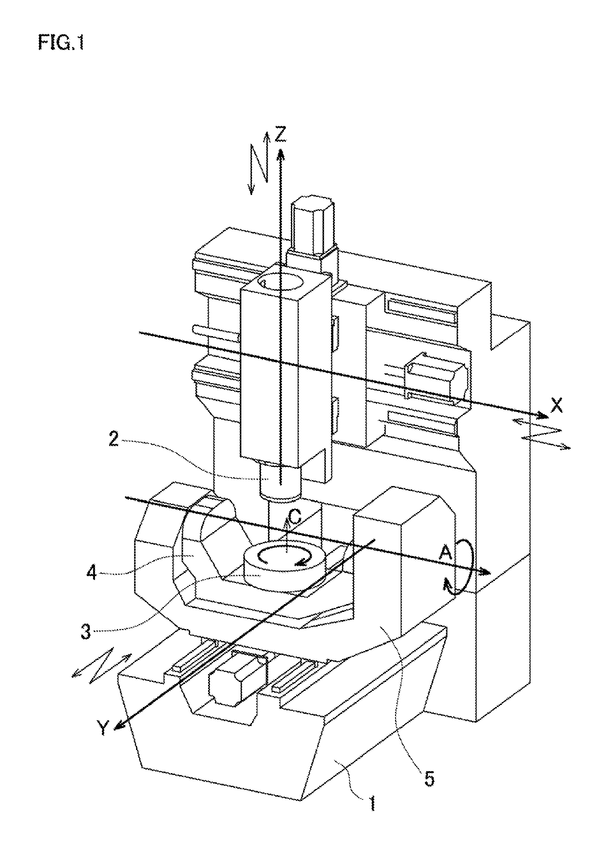
[0060]FIG. 1 is a schematic diagram of a machining center, which is one configuration of a machine tool that includes three translational axes orthogonal to one another and two rotation axes orthogonal to one another. A motion of two degrees of freedom for translation of a main spindle 2 in an X-axis and a Z-axis, which are the translational axes and are orthogonal to one another, is possible with respect to a bed 1. A motion of one degree of freedom for rotation of a table 3 in a C-axis, which is the rotation axis, is possible with respect to a cradle 4. A motion of one degree of freedom for rotation of the cradle 4 in an A-axis, which is the rotation axis orthogonal to the C-axis, is possible with respect to a trunnion 5. A motion of one degree of freedom for translation of the trunnion 5 in a Y-axis, which is the translational axis and orthogonal to the X-axis and the Z-axis, is possible with respec...


PUM


Abstract

A position measurement method to measure a position of an object in a machine tool includes a tool sensor position acquisition stage, a reference block position acquisition stage, a relative position calculation stage, a reference tool position acquisition stage, a position measurement sensor measurement stage, a length compensation value calculation stage, and a position measurement stage. In the position measurement stage, the measurement position of the object is compensated using a length direction compensation value of a position measurement sensor calculated in the length compensation value calculation stage. The object is measured by the position measurement sensor installed to a main spindle.

Description

BACKGROUND[0001]This application claims the benefit of Japanese Patent Application Numbers 2016-083859 filed on Apr. 19, 2016 and 2016-251488 filed on Dec. 26, 2016, the entirety of which is incorporated by reference.TECHNICAL FIELD[0002]The disclosure relates to a position measurement method and a position measurement system to measure a position of an object such as a tool and a workpiece in a machine tool.RELATED ART[0003]There has been employed a method where a machine tool, which performs processes on a workpiece mounted on a table with a tool installed to a main spindle and rotated, automatically measures and compensates a length of the tool and a position of the workpiece for highly accurate processes.[0004]The automatic measurement method for the tool length uses, for example, a laser sensor 10 as illustrated in FIG. 2 and a touch sensor 20 as illustrated in FIG. 3.[0005]Firstly, the laser sensor 10 includes a light emitting portion 11, a light receiving portion 12, and a ba...

Claims


Application Information

Patent Timeline
Patent Type & Authority Patents(United States)
IPC IPC(8): G01B5/016B23Q17/22G01B5/008
CPCG01B5/016G01B5/008B23Q17/22B23Q17/2241B23Q17/0923B23Q17/2461B23Q17/2485
Inventor KANBE, REIJIMATSUSHITA, TETSUYA
Owner OKUMA CORP
Learn More