Hand dryer device

a hand dryer and driving technology, applied in the field of hand dryers, can solve the problems of reducing the life of the device, affecting the convenience of use, so as to achieve the effect of improving the convenient life and strong airflow

a hand dryer and driving technology, applied in the field of hand dryers, can solve the problems of reducing the life of the device, affecting the convenience of use, so as to achieve the effect of improving the convenient life and strong airflow

US10362910B2Inactive Publication Date: 2019-07-30CHICONY POWER TECH CO LTD

Image

  • Hand dryer device
  • Hand dryer device
  • Hand dryer device

Examples


Embodiment Construction

[0029]The present disclosure will be apparent from the following detailed description, which proceeds with reference to the accompanying drawings, wherein the same references relate to the same elements.

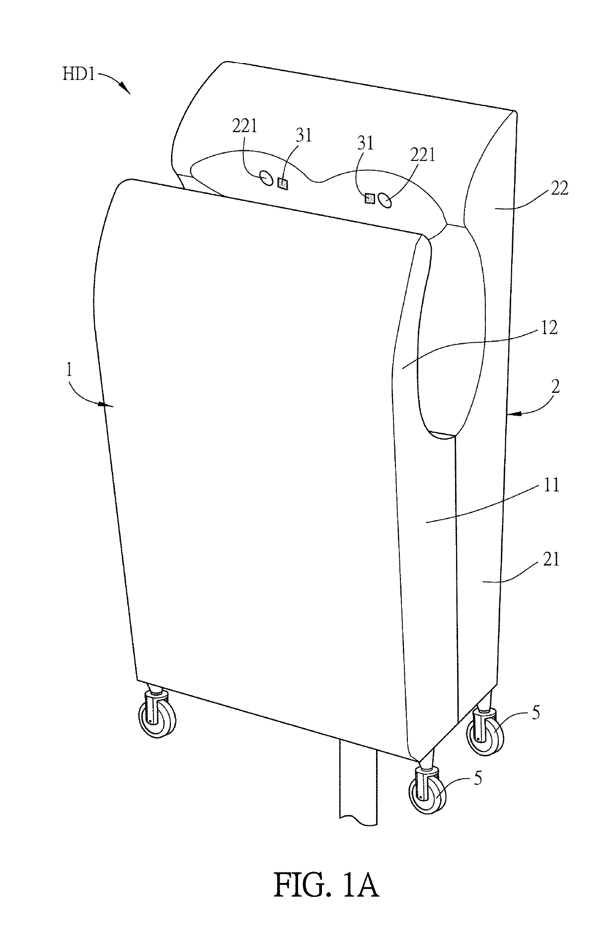
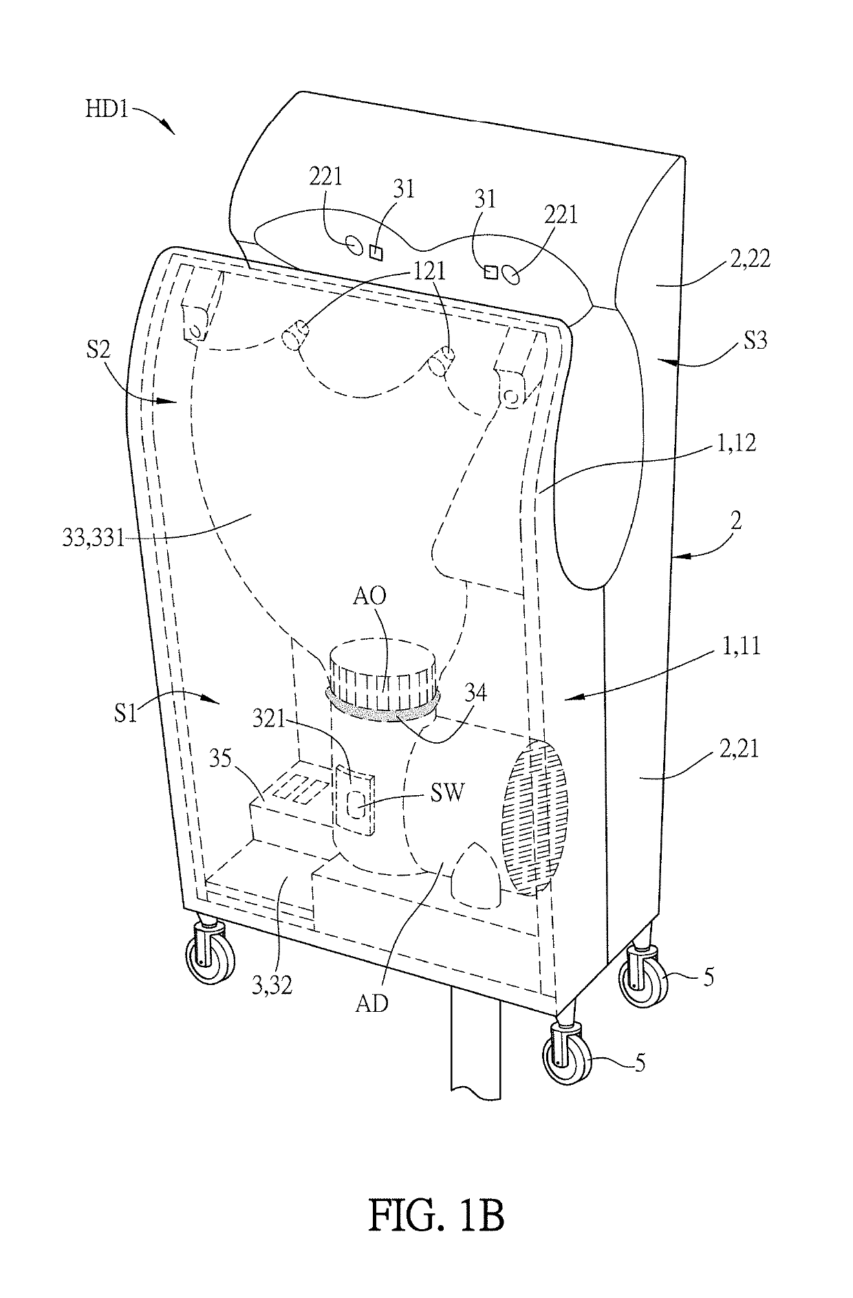
[0030]The basic structure and the features of a hand dryer device according to an embodiment of the disclosure will be described hereinafter with reference to FIGS. 1A to 1C. FIG. 1A is a schematic diagram showing a hand dryer device according to an embodiment of the disclosure, FIG. 1B is a perspective view of the hand dryer device of FIG. 1A, and FIG. 1C is a perspective side view of the hand dryer device of FIG. 1A. In order to make the figures more clear and comprehensive, FIGS. 1B and 1C only show an airflow guiding structure disposed at one side of the first and second housings. In practice, it is possible to configure two airflow guiding structures at two sides of the first and second housings depending on the requirement and design.

[0031]This disclosure provides a hand dryer ...


PUM


Abstract

A hand dryer device cooperated with an airflow driver includes a first housing, a second housing, and an airflow driving unit. The first housing has a first body and a first extension portion. The second housing has a second body and a second extension portion. The second body is connected to the first body for defining an accommodating space, and the first and second extension portions together form a concave annular structure having an extension space. The airflow driving unit includes a sensor, a control module and an airflow guiding structure. The sensor is disposed on the outer surface of the first housing and / or the second housing. The sensor detects and outputs a sensing signal. The control module receives the sensing signal and outputs a control signal. The airflow guiding structure is disposed adjacent to an air outlet and extends to the extension space.

Description

CROSS REFERENCE TO RELATED APPLICATIONS[0001]This Non-provisional application claims priority under 35 U.S.C. § 119(a) on Patent Application No(s). 106127456 filed in Taiwan, Republic of China on Aug. 14, 2017, the entire contents of which are hereby incorporated by reference.BACKGROUNDTechnology Field[0002]The present disclosure relates to a hand driving device that can cooperate with an airflow driver.Description of Related Art[0003]The current home appliances are developed to achieve more efficiency and have more additional functions. Some home appliances, which can generate strong airflows (e.g. wireless vacuum cleaners, hair dryers and the likes), are used for temporary and are mostly rested. However, these devices occupy a certain space for storage, and the internal components thereof may easily damage to reduce the lifetime of the devices if the devices are not frequently used.[0004]Since the hand dryer is expensive and is not easily installed, it is not popularized in every ...

Claims


Application Information

Patent Timeline
30 Jul 2019
Publication
US10362910B2
IPC
A47K10/48; F26B21/12; F26B25/16; F26B21/00
CPC
A47K10/48; F26B21/001; F26B25/16; F26B21/12; F26B21/004
Inventors
CHOU, CHEN-SHI