
Fan blades special for turbine airflow classifier

A classifier and fan blade technology, applied in the direction of separating solids from solids with airflow, solid separation, chemical instruments and methods, etc., can solve problems such as easy to rust, easy to bend, and low service life of fan blades, and achieve The effect of stabilizing chemical properties, improving service life, and high structural strength

Pending Publication Date: 2018-06-12
ZHENGZHOU LION TIGER ABRASIVE MATERIALS & ABRASIVE TOOLS CO LTD
View PDF0 Cites 0 Cited by
  • Summary
  • Abstract
  • Description
  • Claims
  • Application Information

AI Technical Summary

Problems solved by technology

Under the action of fan suction, the material moves to the classification area from the inlet at the lower end of the classifier with the updraft at high speed. Under the action of the strong centrifugal force generated by the high-speed rotating classifying turbine, the coarse and fine materials are separated, and the fine particles that meet the particle size requirements pass through the classification. The gap between the wheel blades enters the cyclone separator or dust collector to collect, and the coarse particles entrain some fine particles to hit the wall, and the speed disappears, and then descends along the cylinder wall to the secondary air outlet, and the strong elutriation of the secondary air separates the coarse and fine particles The particles rise to the classification area for secondary classification, and the coarse particles descend to the discharge port to be discharged. The airflow classifier is equipped with turbine blades. The traditional blades are only equipped with an outer ring and no inner ring, resulting in the blade Strong airflow cannot be generated, the wind flow is very small, which cannot meet the needs of work, and there is no reversing block on the traditional fan blades, the fan blades cannot change the wind direction at any time during work, and the traditional fan blades use iron material components , the chemical properties of the iron material are unstable, and it is easy to rust, and the hardness of the iron material component is not high, and it is easy to bend, which leads to the short service life of the fan blade and cannot meet people's needs

Method used


Image

  • Fan blades special for turbine airflow classifier
  • Fan blades special for turbine airflow classifier
  • Fan blades special for turbine airflow classifier

Examples


Embodiment Construction

[0014] The following will clearly and completely describe the technical solutions in the embodiments of the present invention with reference to the accompanying drawings in the embodiments of the present invention. Obviously, the described embodiments are only some, not all, embodiments of the present invention. Based on the embodiments of the present invention, all other embodiments obtained by persons of ordinary skill in the art without making creative efforts belong to the protection scope of the present invention.

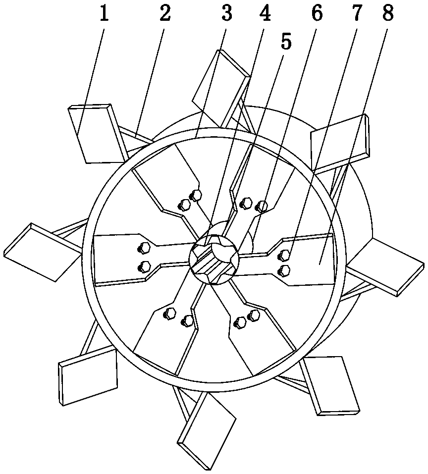
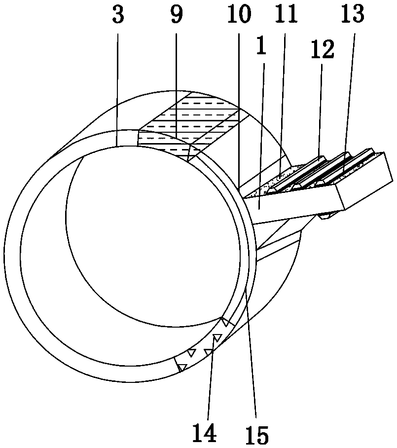
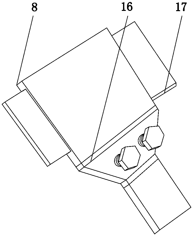
[0015] see Figure 1-3 , an embodiment provided by the present invention: a special fan blade for a turbine airflow classifier, including a first fan blade 1, a second fan blade 8, a guide rail 11, a smart chip 14 and an elongated fan blade 17, the first fan blade 1 It is connected with the connecting frame 2 by bolts 7, and eight first fan blades 1 are installed, the first fan blade 1 and the connecting frame 2 are installed in the chute 10, and the chute 10 ...


PUM


Abstract

The invention discloses fan blades special for a turbine airflow classifier. The fan blade comprises first fan blades, second fan blades, guide rails, intelligent chips and extension fan blades, wherein the first fan blades and connection frames are connected through bolts, and eight first fan blades are arranged; the first fan blades and the connecting frames are arranged in sliding grooves, andthe sliding grooves are formed in the outer wall of an outer ring; the second fan blade are arranged on the outer wall of an inner ring through fixing plates, and an electric plate is arranged insidethe outer ring; the guide rails are laid on the outer walls of the first fan blades, furthermore, the guide rails are connected with sliding blocks in a sliding mode, and the sliding blocks are fixedat the bottoms of reversing plates; and the extension fan blades arranged on the left side and the right side of each first fan blade, and blade storage chambers are arranged in the first fan blades.According to to the fan blades special for the turbine airflow classifier, strong airflow can be generated, and the air supply amount is greatly increased; and the reversing plates capable of automatically changing positions are further arranged on the fan blades so that the wind direction can be changed by changing the positions of the reversing plates in working, and requirements of working aremet.

Description

technical field [0001] The invention relates to the technical field of classifier equipment, in particular to a special fan blade for a turbine air classifier. Background technique [0002] The airflow classifier is a kind of airflow classification equipment. The classifier, cyclone separator, dust collector and induced draft fan form a classification system. Under the action of fan suction, the material moves to the classification area from the inlet at the lower end of the classifier with the updraft at high speed. Under the action of the strong centrifugal force generated by the high-speed rotating classifying turbine, the coarse and fine materials are separated, and the fine particles that meet the particle size requirements pass through the classification. The gap between the wheel blades enters the cyclone separator or dust collector to collect, and the coarse particles entrain some fine particles to hit the wall, and the speed disappears, and then descends along the c...

Claims


Application Information

Patent Timeline
Patent Type & Authority Applications(China)
IPC IPC(8): B07B7/083B07B11/02
CPCB07B7/083B07B11/02
Inventor 邓彬杨振伟邓全一王龙柱
Owner ZHENGZHOU LION TIGER ABRASIVE MATERIALS & ABRASIVE TOOLS CO LTD
Learn More