Control device for internal combustion engine

a control device and internal combustion engine technology, applied in the direction of electric control, combustion engines, machines/engines, etc., can solve the problems of large torque shocks that are liable to be generated, narrow width in which the air-fuel ratio can shift toward a rich direction, etc., to achieve smooth operation, good combustibility, and change the flow velocity of intake air

Inactive Publication Date: 2016-12-29
TOYOTA JIDOSHA KK
View PDF3 Cites 1 Cited by
  • Summary
  • Abstract
  • Description
  • Claims
  • Application Information

AI Technical Summary

Benefits of technology

[0040]According to the first aspect discussed above, the flow velocity of intake air can be changed by opening / closing a flow velocity adjusting valve that is positioned downstream of a throttle valve. Further, according to the embodiment of the present invention, the internal combustion engine can be operated in a lean mode in a low-speed and low-load region and operated in a stoichiometric mode in a high-speed and high-load region. In a leaning process of the internal combustion engine, the flow velocity adjusting valve is maintained in an open state over the entire region of the stoichiometric mode, and is changed to a closed state after switching to the lean mode is performed. The intake air amount decreases when the flow velocity adjusting valve is changed from an open state to a closed state, and in the embodiment of the present invention this change is performed in the lean mode. Because the output torque in the lean mode is determined by the fuel injection amount, a change in the air amount affects a little to the torque. Therefore, according to the embodiment of the present invention, torque shock due to closing of the flow velocity adjusting valve can be suppressed to a small amount.
[0041]According to the second aspect discussed above, in an enriching process of the internal combustion engine, the flow velocity adjusting valve is maintained in a closed state over the entire region of the lean mode, and is switched to an open state at or after a time that the stoichiometric mode is implemented. Therefore, during operation in the lean mode, a strong air flow arises in the cylinders over the entire region of operation, and good combustibility is obtained. Further, in the stoichiometric mode, the ignitability of the air-fuel mixture does not increase to excessively high level, since an air flow in the cylinders is suppressed. Therefore, according to the embodiment of the present invention the internal combustion engine can be smoothly operated during an enriching process.
[0042]According to the third aspect discussed above, in the enriching process, the operating state of the internal combustion engine reaches an opening / closing boundary at or after a time that the operating state reaches an air-fuel ratio boundary. Therefore, according to the embodiment of the present invention, a time point at which the flow velocity adjusting valve changes to an open state in an enriching process can be surely at or after a time point at which the lean mode is switched to the stoichiometric mode. Further, according to the embodiment of the present invention, in the leaning process, the operating state does not reach the opening / closing boundary unless the internal combustion engine decelerates to a low-speed and low-load side relative to the air-fuel ratio boundary. Consequently, according to the embodiment of the present invention, a time point at which the flow velocity adjusting valve is switched from an open state to a closed state during the leaning process can be surely after switching from the stoichiometric mode to the lean mode.
[0043]According to the fourth aspect discussed above, a relation between the air-fuel ratio boundary and the opening / closing boundary that the third aspect discussed above requires can be simply and easily realized by using different air-fuel ratio boundaries in the enriching process and in the leaning process.
[0044]According to the fifth aspect discussed above, an air-fuel ratio boundary that satisfies the relation that the third aspect discussed above requires can be reliably established at a time point at which the leaning process is started.
[0045]According to the sixth aspect discussed above, in the leaning process, the air-fuel ratio of the air-fuel mixture can be corrected to the rich side immediately after the flow velocity adjusting valve is switched to a closed state. Therefore, according to the embodiment of the present invention, an amount by which torque decreases due to a decrease in the air amount following a valve closing operation can be compensated for by enrichment of the air-fuel ratio. Enrichment of the air-fuel ratio cannot be performed so as to exceed a rich limit for a three-way catalyst to purify exhaust gas. Therefore, in the stoichiometric mode, the width in which the air-fuel ratio can shift toward a rich direction is inevitably narrow. In the present invention, since a valve closing operation of the flow velocity adjusting valve is performed in the lean mode, it is possible to secure a large width in which the air-fuel ratio can shift toward the rich direction when the flow velocity adjusting valve closes. Therefore, according to the embodiment of the present invention, torque shock due to enrichment of the air-fuel ratio can be absorbed, and the internal combustion engine can be continued to be operated extremely smoothly during the leaning process.

Problems solved by technology

However, the above described flow control valve changes the effective area of the intake passage due to an opening / closing operation.
Consequently, in the aforementioned internal combustion engine, a large torque shock is liable to be generated when the mode is switched from the stoichiometric mode to the lean mode.
Therefore, in the stoichiometric mode, the width in which the air-fuel ratio can shift toward a rich direction is inevitably narrow.

Method used


Image

  • Control device for internal combustion engine
  • Control device for internal combustion engine
  • Control device for internal combustion engine

Examples


first embodiment

[Modification of First Embodiment]

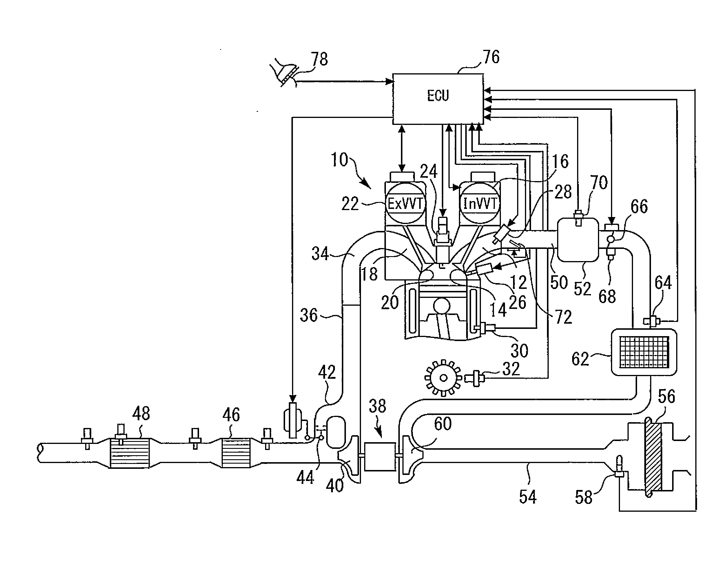
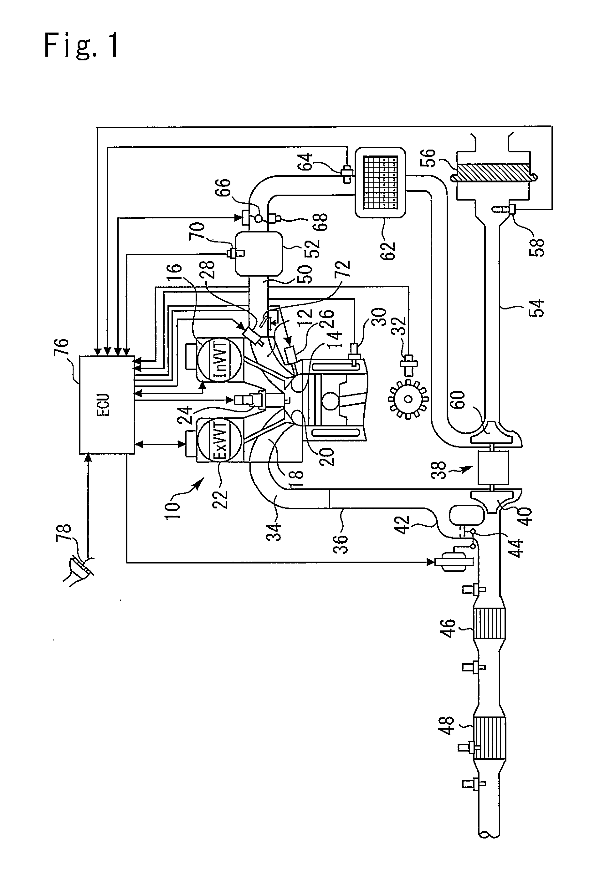
[0132]In the above described first embodiment, a flow velocity adjusting valve that is installed in an intake passage is limited to the TCV 72. However, the configuration of the present invention is not limited thereto. The flow velocity adjusting valve may be any valve mechanism that can generate an air flow inside a cylinder that improves the combustibility in the lean mode, and as long as that function is satisfied, the flow velocity adjusting valve may be, for example, a component that generates an air flow accompanying a tumble flow.

[0133]Further, in the above described first embodiment, the air-fuel ratio boundary 96 that is used in the leaning process is set between the operating state of the internal combustion engine 10 and the opening / closing boundary 84 when the deceleration determination (step 102) regarding the internal combustion engine 10 is newly affirmed. However, this setting is not essential in the present invention. That is, a co...


PUM


Abstract

Embodiments of the present invention relate to a control device for an internal combustion engine. The control device controls an internal combustion engine that includes a throttle valve and a TCV. The control device selectively implements a stoichiometric mode that causes the internal combustion engine to operate in a stoichiometric region, and a lean mode that causes the internal combustion engine to operate in a lean region. The control device executes a process that places the TCV in a closed state for generating a tumble flow, and a process that places the TCV in an open state for suppressing a tumble flow. A process that switches the TCV from the open state to the closed state is executed during implementation of the lean mode.

Description

BACKGROUND OF THE INVENTION[0001]Field of the Invention[0002]Embodiments of the present invention relate to a control device for an internal combustion engine. More particularly, embodiments of the present invention relate to a control device for an internal combustion engine that is suitable for being used on a vehicle.[0003]Background Art[0004]Japanese Patent Laid-Open No. 2004-293484 discloses an internal combustion engine that appropriately switches an operating mode between a stoichiometric mode that causes the internal combustion engine to operate at an air-fuel ratio around stoichiometry, and a lean mode that causes the internal combustion engine to operate at a lean air-fuel ratio. The aforementioned internal combustion engine includes a flow control valve at a position that is downstream of a throttle valve. When the flow control valve partly closed in an intake passage, the flow velocity of intake air increases and thereby a tumble flow inside a combustion chamber is stren...

Claims


Application Information

Patent Timeline
Patent Type & Authority Applications(United States)
IPC IPC(8): F02D41/30
CPCF02D41/3017F02D41/1475F02D41/3064F02D41/307F02B31/06F02D41/0002F02D2041/0015Y02T10/12Y02T10/40
Inventor KORENAGA, SHINGO
Owner TOYOTA JIDOSHA KK
Why Eureka
Try Eureka