Indoor unit for air conditioner

An air conditioner and indoor unit technology, applied in the field of indoor units, can solve problems such as inapplicability, and achieve the effects of simple structure and changing the flow rate of exhaust air

Inactive Publication Date: 2006-03-29
LG ELECTRONICS (TIANJIN) APPLIANCES CO LTD
View PDF0 Cites 6 Cited by
  • Summary
  • Abstract
  • Description
  • Claims
  • Application Information

AI Technical Summary

Problems solved by technology

[0010] Therefore, as mentioned above, the indoor unit that discharges a small amount of air from the side is not suitable for other places except the I-shaped room.

Method used


Image

  • Indoor unit for air conditioner
  • Indoor unit for air conditioner
  • Indoor unit for air conditioner

Examples


Embodiment Construction

[0042] Preferred embodiments according to the present invention will be described in detail below in conjunction with the accompanying drawings.

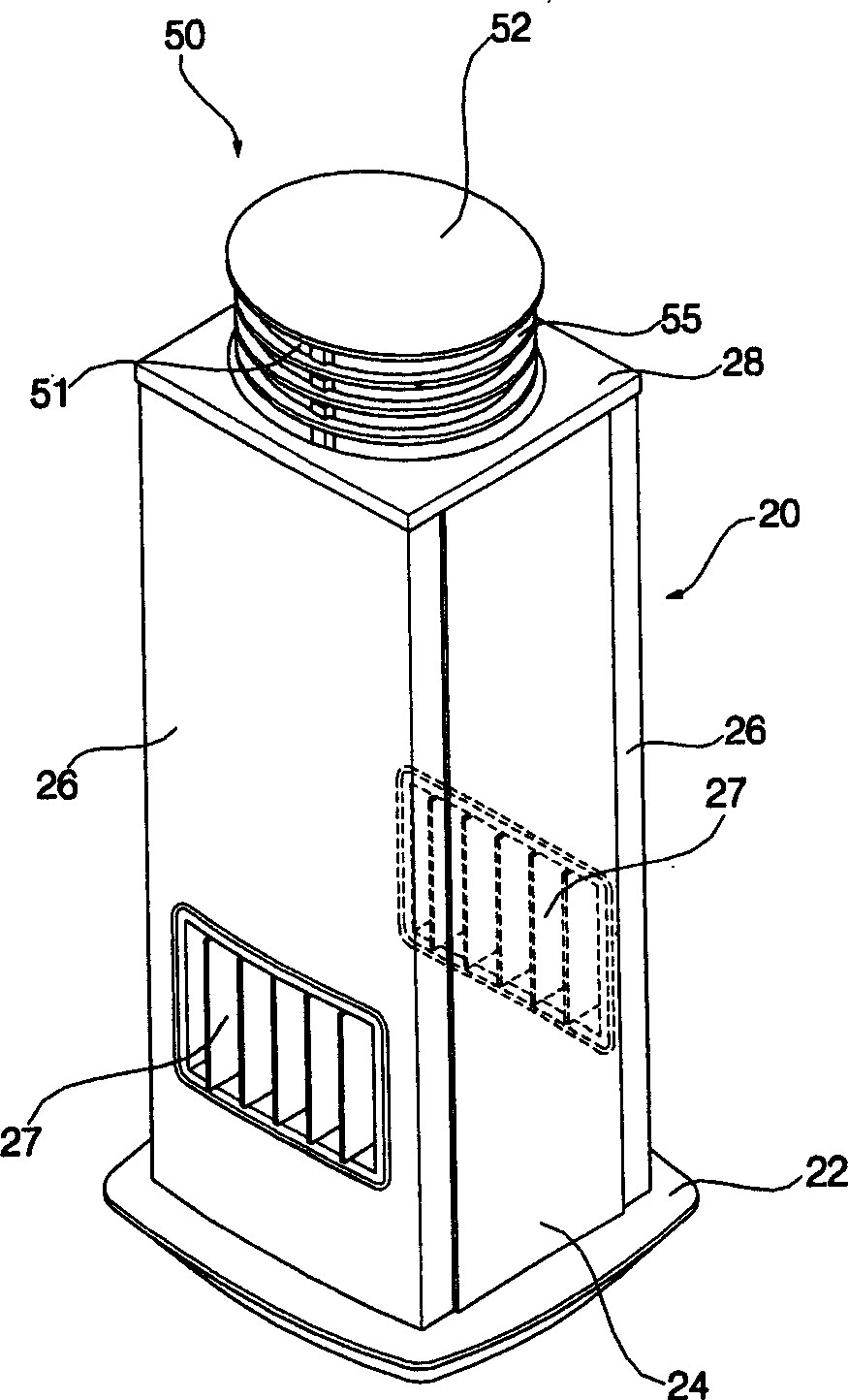
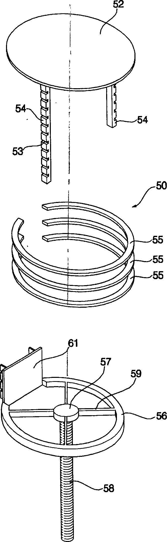
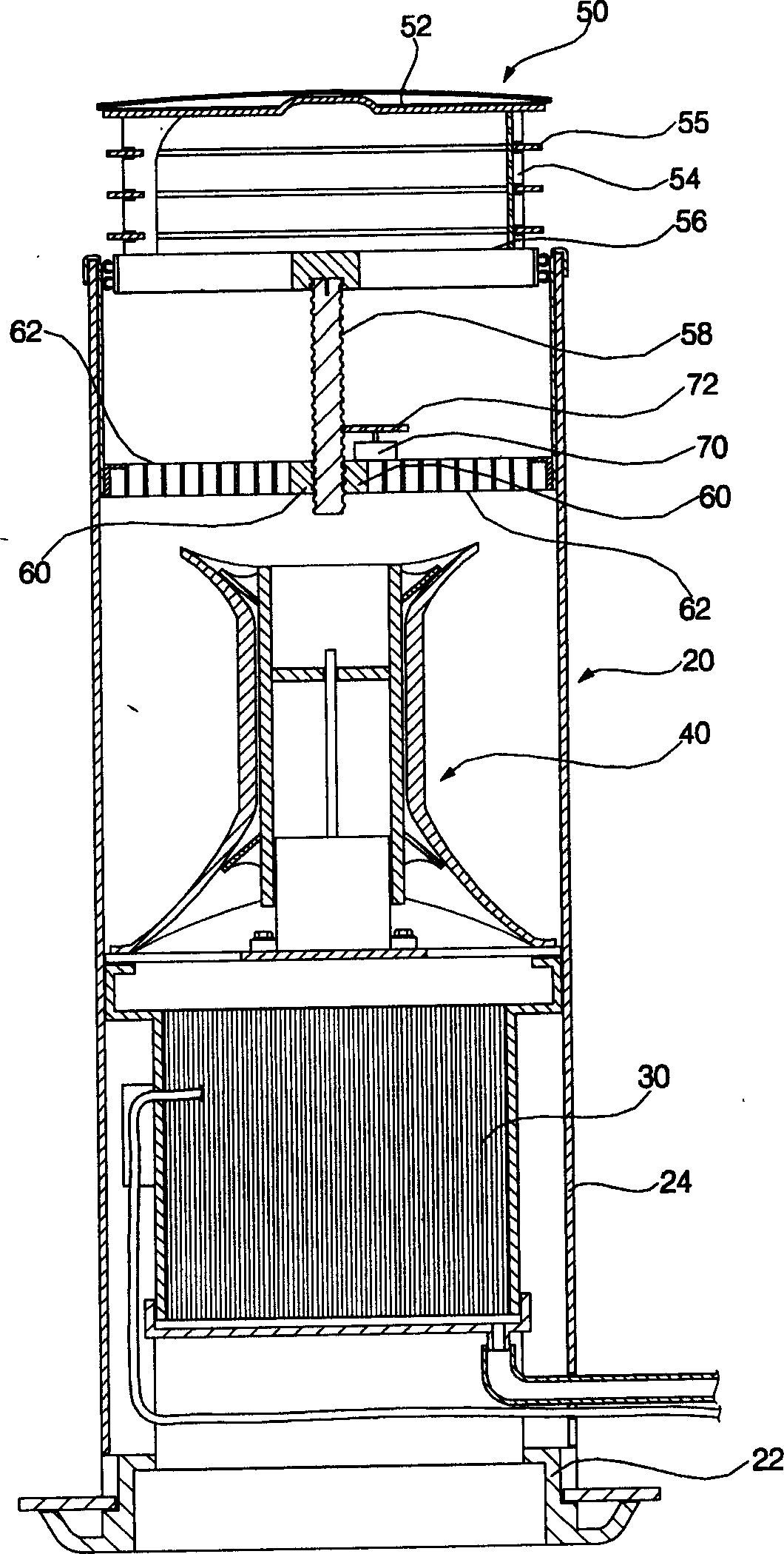
[0043] figure 1 Showing the first embodiment of the present invention, it is a perspective view of an indoor unit of an air conditioner, figure 2 yes figure 1 Exploded oblique view of the middle discharge port assembly, image 3 yes figure 1 The cross-sectional view of Figure 4 is figure 1 Schematic diagram of the operation of the outlet assembly before and during operation.

[0044] Such as figure 1 As shown in FIG. 4, the structure according to the first embodiment of the present invention includes: a housing 20; an indoor heat exchanger 30 for exchanging heat between indoor air and refrigerant; and an indoor blower for discharging the air inside the housing 20 to the outside of the housing 20 40 ; to discharge the air discharged by the indoor blower 40 to the outside of the housing 20 , the discharge outlet assembly 5...


PUM


Abstract

The indoor machine of air conditioner includes external shell whose upper portion has an opening; discharge outlet component which can be lifted and fallen along the inner side of external shell and formed into discharge outlet; screw bolt formed on the lower side of discharge outlet component for lifting and falling the discharge outlet component; fixing component on which a nut portion engaged with screw bolt is formed and moving device for vertically moving screw bolt.

Description

technical field [0001] The present invention relates to an indoor unit of an air conditioner, more specifically, an indoor unit in which a discharge port is formed by a discharge port assembly that can move up and down. Background technique [0002] Figure 5 It is an oblique view of an air conditioner indoor unit in the prior art, Image 6 yes Figure 5 Internal exploded oblique view of . [0003] Such as Figure 5 and 6 As shown, the indoor unit of the air conditioner according to the prior art includes: an indoor heat exchanger 1 for exchanging heat between indoor air and refrigerant; an indoor blower 2 for improving the efficiency of the indoor heat exchanger 1 and delivering air to the room; It consists of a housing 5 with a suction port 3 and a discharge port 4. [0004] The casing 5 includes a chassis 6, a front casing 7 formed with a suction port 3 and a discharge port 4, and a rear casing 8 on which the indoor heat exchanger 1 and the indoor blower 2 are mounted....

Claims


Application Information

Patent Timeline
Patent Type & Authority Applications(China)
IPC IPC(8): F24F1/00F24F13/06F24F13/08
Inventor 金丙太
Owner LG ELECTRONICS (TIANJIN) APPLIANCES CO LTD
Why Eureka
Try Eureka