Spiral heat exchange tube

A technology of heat exchange tube and helical shape, which is applied in the field of heat exchange tubes with enhanced heat exchange structure, can solve the problems of difficulty, limited flow heat transfer coefficient, excessive helix angle, etc., achieve high economy and prolong service life , the effect of small resistance

Inactive Publication Date: 2009-08-26
CHONGQING UNIV
View PDF1 Cites 6 Cited by
  • Summary
  • Abstract
  • Description
  • Claims
  • Application Information

AI Technical Summary

Problems solved by technology

However, because the helix angle is too large, the improvement of the convective heat transfer coefficient is very l

Method used


Image

  • Spiral heat exchange tube
  • Spiral heat exchange tube
  • Spiral heat exchange tube

Examples


Embodiment Construction

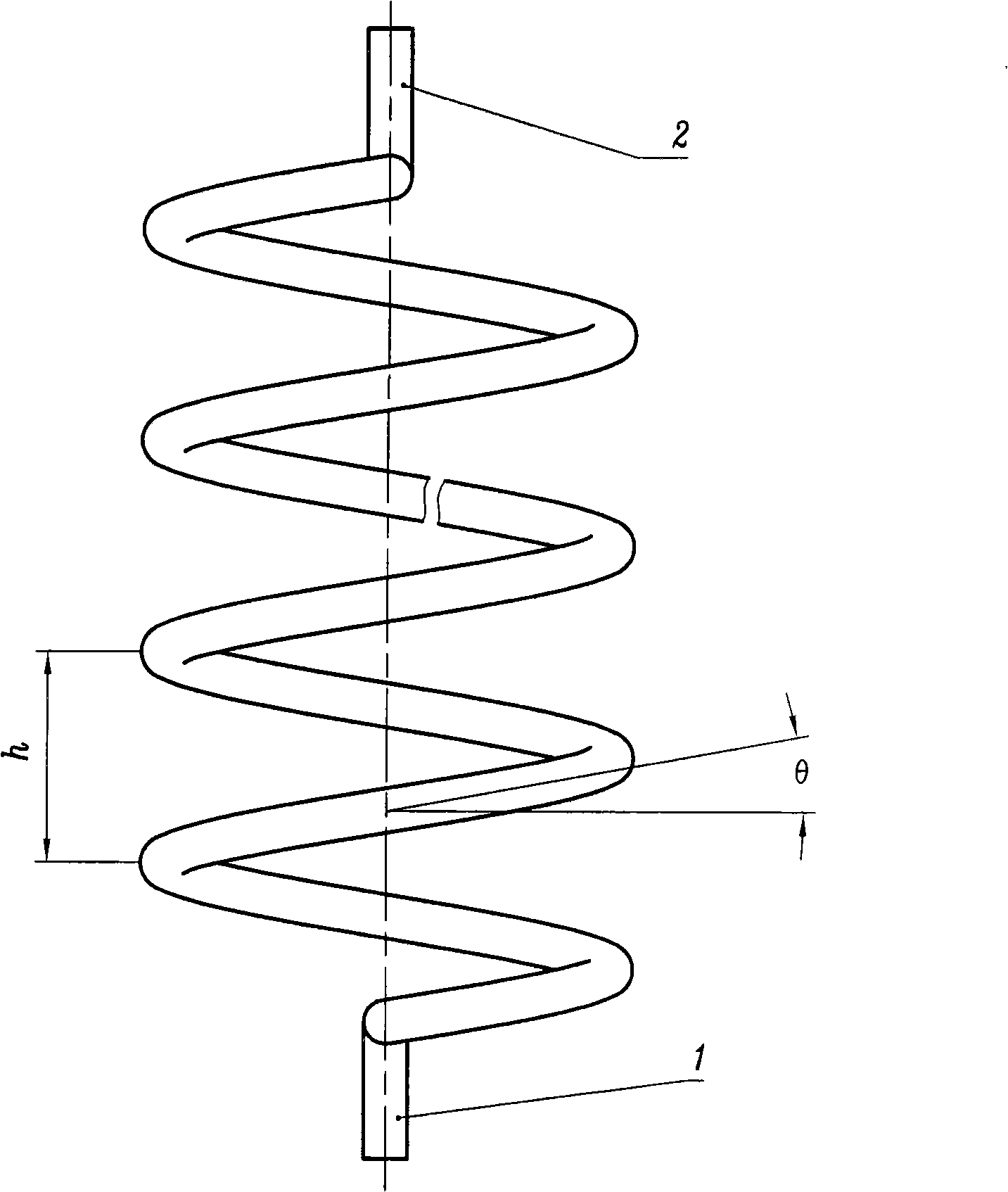
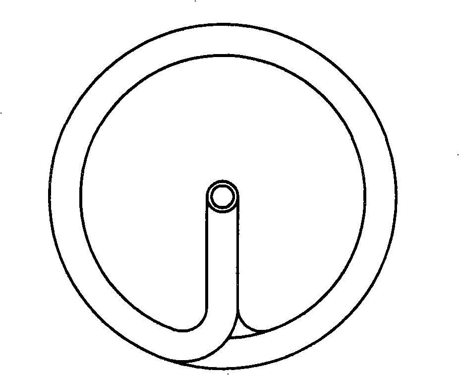
[0019] A helical heat exchange tube, the part that performs heat exchange is helical (refer to figure 1 , 2 ). In the present invention, the cross-section of the heat exchange tube is circular, the helix angle θ of the heat exchange part is 10° to 30°, and the pitch h is 3 to 6 times the outer diameter of the heat exchange tube; The two ends of the heat exchange tube are fixed (usually welded) on the heat exchanger, the inlet end 1 and the outlet end 2 of the heat exchange medium are the same as the prior art, and they are all straight pipes (obviously, they are only a small section) ). According to the actual installation situation, this short section of straight pipe at the inlet end 1 or outlet end 2 can be directly extended or bent with the two ends of the spiral pipe section, or can be bent to the axis of them or one of them and the spiral pipe section. A state where the axes overlap (due to the obviousness, the accompanying drawing only draws the structure in which th...


PUM

PropertyMeasurementUnit
Helix angleaaaaaaaaaa

Abstract

The present invention provides a spiral heat exchange tube of which the cross section is annular, wherein, the helix angle of part with the heat exchange function is 10 DEG to 30 DEG. The thread pitch is 3-6 times of the outer diameter of the heat exchange tube. The inlet end 1 and outlet end 2 of heat exchange medium, which fix two ends of heat exchange tube to the heat exchanger, are equally one segment of straight tube. When the spiral heat exchange tube is installed into the heat exchanger, the pressure and flow velocity of medium (hot water, etc.) flowing through the heat exchanger tube can be continuously changed with a microseism mode. Compared with the prior heat exchange tube, the spiral heat exchanger according to the invention not only has high heat transmission efficiency, but also has strong self-cleaning and anti-scaling capability. The space can be effectively used and the capability of large heat transmission in small space is realized. The integrated energy-saving plan provided by the invention has the advantages of simple structure and low system cost. Relative to the prior self-cleaning heat exchange tube, the spiral heat exchange tube of the invention further has the advantages of smaller resistance, simpler structure, low cost, and suitability for quickly generalized and applied in practice.

Description

technical field [0001] The invention relates to a heat exchange tube in a heat exchanger, in particular to a heat exchange tube with an enhanced heat exchange structure. Background technique [0002] Heat exchangers, also known as heat exchangers, are general-purpose process equipment widely used in petroleum, chemical, power, energy, metallurgy, aviation, vehicles, refrigeration, food, environmental protection and many other industrial sectors. The missing key components occupy a very important share in material consumption, power consumption and engineering investment. At present, the energy crisis is becoming more and more serious, and the social, economic, and environmental issues centered on energy are becoming more and more prominent. Energy conservation and rational and effective use of energy are particularly important. [0003] To improve the efficiency of the heat exchanger, that is, to enhance the heat transfer of the heat exchanger, certain technical measures ca...

Claims


Application Information

Patent Timeline
IPC IPC(8): F28F1/00F28F9/00F28F13/10F28F13/12F28F13/02
Inventor 串禾詹武刚张瑜江涛武培高俊敏伍劲涛申罗恒
Owner CHONGQING UNIV
Why Eureka
Try Eureka