Supercharge Your Innovation With Domain-Expert AI Agents!

Support removal tool for additive manufacture

Active Publication Date: 2019-07-30
GENERAL ELECTRIC CO
View PDF12 Cites 0 Cited by
  • Summary
  • Abstract
  • Description
  • Claims
  • Application Information

AI Technical Summary

Benefits of technology

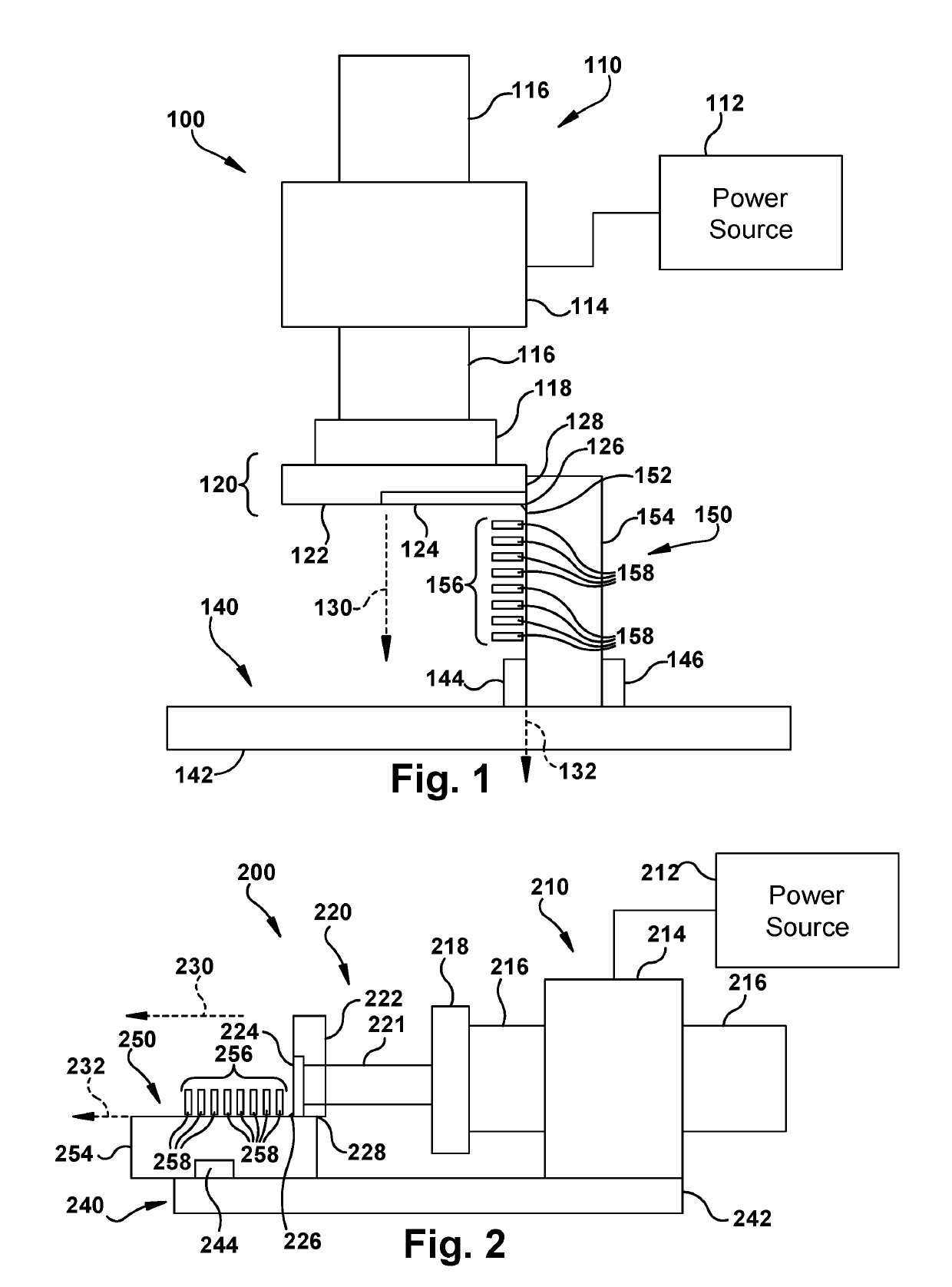
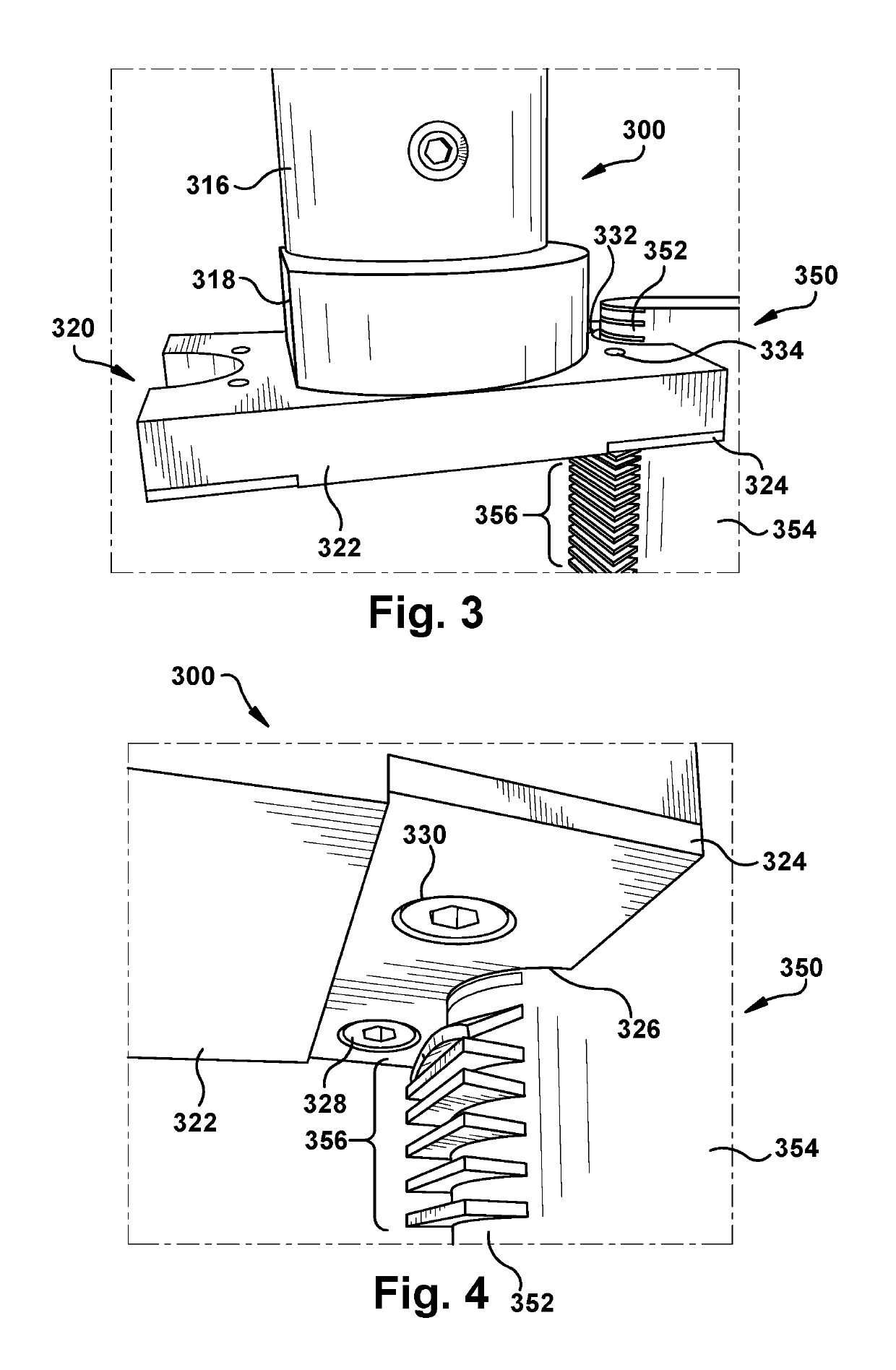
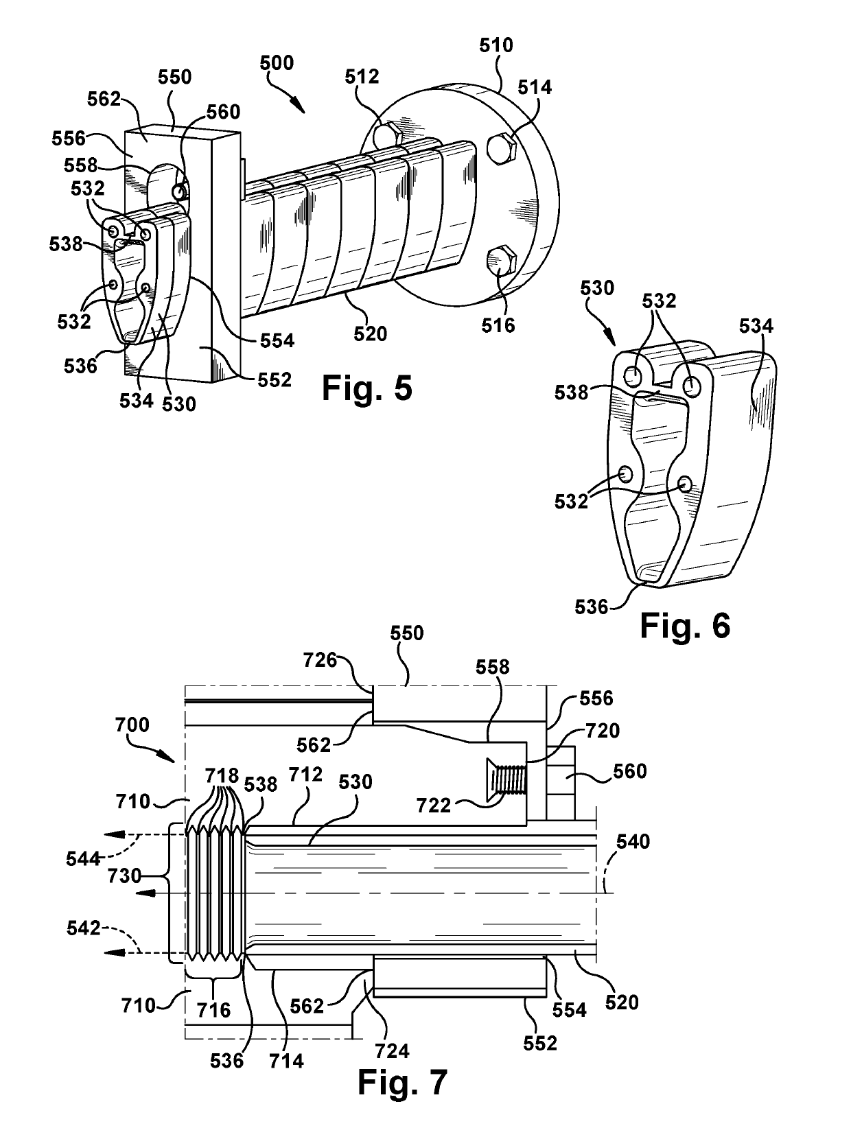
The invention provides a laser-sintered component that has a surface with a support structure and at least one breakable joint. The component also has a mounting receptacle for a cutting surface that can be moved along a cutting path to separate the support structure from the surface of the component. The cutting surface has a complementary shape to the component surface and a cutting edge to achieve precise separation. This design allows for precise and safe cutting of the component surface and support structure.

Problems solved by technology

One challenge associated with additive manufacturing includes maintaining the shape of a component before the manufacturing process completes.

Method used


Image

  • Support removal tool for additive manufacture
  • Support removal tool for additive manufacture
  • Support removal tool for additive manufacture

Examples


Embodiment Construction

[0021]In the following description, reference is made to the accompanying drawings that form a part thereof, and in which is shown by way of illustration specific illustrative embodiments in which the present teachings may be practiced. These embodiments are described in sufficient detail to enable those skilled in the art to practice the present teachings and it is to be understood that other embodiments may be used and that changes may be made without departing from the scope of the present teachings. The following description is, therefore, merely exemplary.

[0022]Where an element or layer is referred to as being “on,”“engaged to,”“disengaged from,”“connected to” or “coupled to” another element or layer, it may be directly on, engaged, connected or coupled to the other element or layer, or intervening elements or layers may be present. In contrast, when an element is referred to as being “directly on,”“directly engaged to,”“directly connected to” or “directly coupled to” another e...


PUM

PropertyMeasurementUnit
Forceaaaaaaaaaa

Abstract

Aspects of the disclosure include a machine and system for support removal and a laser-sintered component compatible with same. A laser-sintered component may have a component surface and at least one laser-sintered support extending from the component surface. A press may move a cutting surface along a cutting path adjacent to the component surface. The cutting surface has a shape complementary to the component surface and at least one cutting edge positioned to separate at least one laser-sintered support from the component surface as the cutting surface moves along the cutting path.

Description

TECHNICAL FIELD[0001]The disclosure relates generally to the removal of supports from laser-sintered components, such as those produced in additive manufacture. More particularly, embodiments of the present disclosure provide machines, tooling attachments, and components for removing support structures with a press machine.BACKGROUND[0002]The pace of change and improvement in the realms of power generation, aviation, and other fields has accompanied extensive research for manufacturing components used in these fields. Conventional manufacture of metallic components generally includes milling or cutting away regions from a slab of metal before treating and modifying the cut metal to yield a part, which may have been simulated using computer models and computer aided design. Manufactured components which may be formed from metal include airfoil components for installation in a turbomachine such as an aircraft engine or power generation system, as well as mechanical components for othe...

Claims


Application Information

Patent Timeline
IPC IPC(8): B26F3/00B33Y40/00B22F3/24B33Y80/00B22F5/00
CPCB26F3/00B22F3/24B22F5/00B33Y40/00B33Y80/00B22F2003/247Y02P10/295B22F2999/00B22F2003/1058B33Y40/20B22F10/47B22F10/66B22F10/40Y02P10/25
Inventor GUBELMANN, FABIANPALYS, DARIUSZ OLIWIUSZVOGT, ERNST
Owner GENERAL ELECTRIC CO
Features
  • R&D
  • Intellectual Property
  • Life Sciences
  • Materials
  • Tech Scout
  • Unparalleled Data Quality
  • Higher Quality Content
  • 60% Fewer Hallucinations
Learn More