Retractable wing

a load-bearing wing and wing body technology, which is applied in the direction of waterborne vessels, hulls, vessel construction, etc., can solve the problems of complex and hazardous mooring alongside quays or pontoons, the configuration of such load-bearing wings is not naturally stable as regards ride height, etc., and achieves simple design and easy and quick retraction

Inactive Publication Date: 2019-07-30
SEABUBBLES
View PDF9 Cites 0 Cited by
  • Summary
  • Abstract
  • Description
  • Claims
  • Application Information

AI Technical Summary

Benefits of technology

[0016]The object of the invention is therefore to wholly or partly remedy the disadvantages of the prior art. In particular the object of the invention is to provide an alternative solution to the existing solutions for retractable load-bearing wings, which is of simple design, allowing the load-bearing wing to be easily and quickly retracted in such a way that it does not give rise to any significant increase in the maximum beam of the hull and thus makes mooring a watercraft easier, while being suitable for all types of existing hulls without any need to modify them and being capable of being applied to any configuration of load-bearing wing, whether of the piercing or immersed type.
[0018]Thus the dimensions of the load-bearing wing are reduced to the sum of the thicknesses of the support leg and the load-bearing plane. The support leg can then be lifted into a retracted position, aligned along the side wall of the hull without any risk of damaging the latter.

Problems solved by technology

On the other hand this configuration is not naturally stable as regards ride height, pitch and roll.
They nevertheless have a number of disadvantages because of their bulk.
Thus a boat fitted with such load-bearing wings is not able to sail at slow speed in shallow water.
Mooring alongside a quay or a pontoon is complicated and hazardous, particularly when the load-bearing wing extends beyond the maximum beam of the boat.
However in the latter case the load-bearing wings generally have a curved profile and the possibilities for constructing profiles of different shape are limited because they are detrimental to the performance and / or cost of the load-bearing wing.
Because the large dimensions of load-bearing wings make mooring in particular very difficult, solutions for retracting them to reduce their dimensions have been envisaged in the past.
Although this system makes it possible to retract a load-bearing wing, it cannot retract it completely so that the boat has the appearance of being without a load-bearing wing.
The telescopic retraction system described appears to be complex to construct and requires the hull of the boat to be altered in order to be able to incorporate it.
Such a system cannot therefore be easily used on any boat and also cannot be applied to any configuration of load-bearing wing.
This document describes a complex retraction system which again makes it necessary to adapt and modify a boat / s hull and is not able to adapt to all configurations of load-bearing wings.
Such a solution is therefore still too complex and costly to be implemented.
This solution also appears to be complex to implement because it requires modification of the boat's hull.
It cannot therefore be easily implemented for any type of boat, nor for any configuration of load-bearing wing.
Furthermore the presence of the guide bar makes it impossible to reduce the boat's draft.
Such solutions are complicated and costly to implement, require modifications to boat hulls and cannot always be adapted to all load-bearing wing configurations.
As a consequence the existing solutions are unsatisfactory.
In fact although they make it possible to shorten a load-bearing wing, by sliding its constituent elements, which nest and slide within each other, these solutions all require changes in the hull of the watercraft and are not appropriate for all load-bearing wing configurations.

Method used


Image

  • Retractable wing
  • Retractable wing
  • Retractable wing

Examples


Embodiment Construction

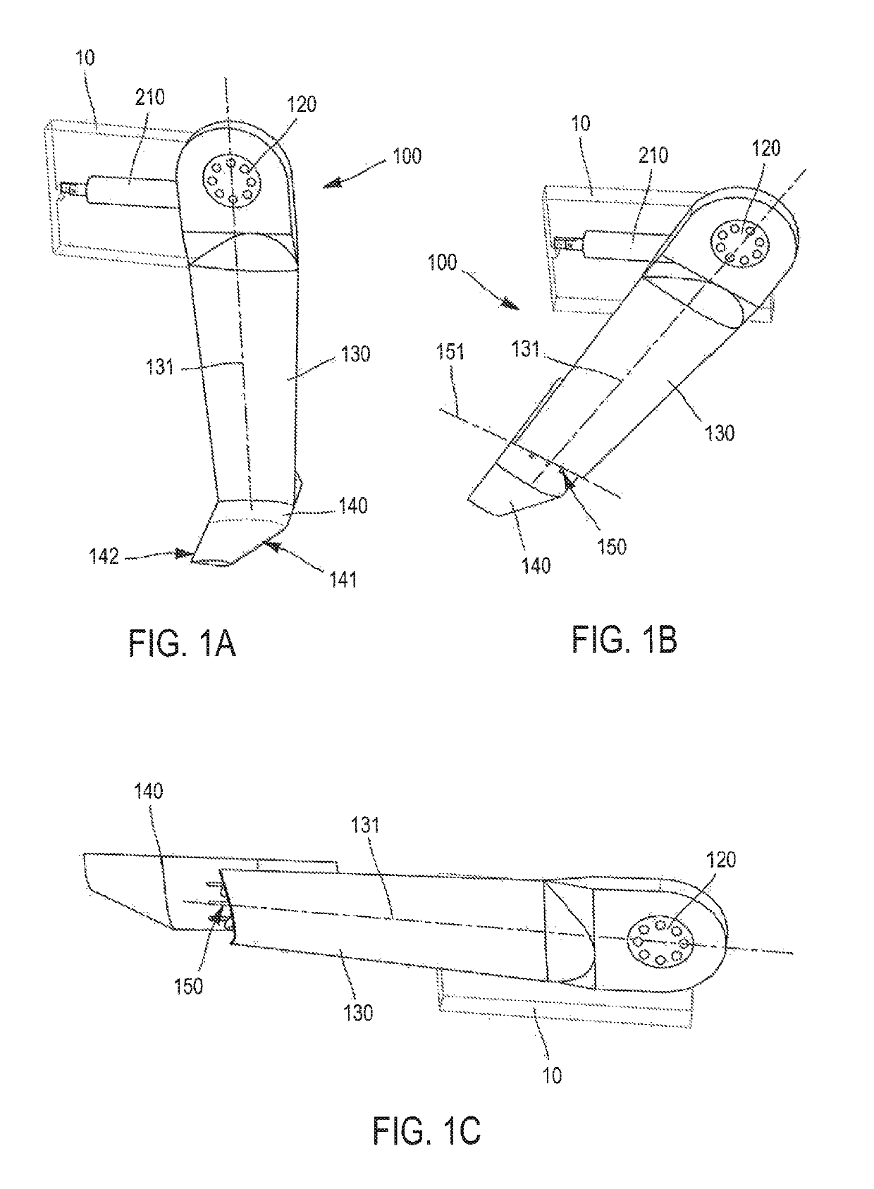
[0044]In the remainder of the description the terms “bow” and “stern” are defined in relation to the hull of a boat and according to its direction of motion. Likewise the terms “upper” or “top” or “above” and “lower” or “bottom” or “below” are defined with respect to the hull and the surface of the water.

[0045]The leading edge of a load-bearing plane is defined as being the edge which first touches the fluid.

[0046]The trailing edge of a load-bearing plane, opposite the leading edge, is the edge to which the fluid flows.

[0047]The angle of incidence, also known as the angle of attack, is the angle that forms the cord or axis of the load-bearing plane with the direction of fluid flow. By “cord” or “axis of the load-bearing plane” is meant the straight line joining the leading edge to the trailing edge. Lift increases with the angle of incidence up to a maximum valise where detachment and loss of lift occurs. In order to have a positive incidence, and therefore positive lift, the leadin...


PUM


Abstract

The invention relates to a retractable wing equipping a watercraft. The wing includes a first support upright, a first end of which engages with the hull of the watercraft and a second end of which supports a first hydrofoil. The wing is characterized in that the first hydrofoil and first support upright engage with one another by way of an articulated connection having a degree of freedom in rotation about an axis perpendicular to a longitudinal axis passing through the ends of the first support upright, allowing the hydrofoil to fold parallel to the longitudinal axis.

Description

CROSS-REFERENCE TO RELATED APPLICATIONS[0001]The present application is the national stage entry of International Parent Application No. PCT / FR2015 / 052319 having a filing date of Sep. 2, 2015, which claims priority to French Patent Application No. 1458227 filed on Sep. 8, 2014, which are incorporated herein in their entirety by reference thereto.BACKGROUND OF THE INVENTION[0002]The invention relates to the field of load-bearing wings, also known by the English term “hydrofoil”, fitted to watercraft. More particularly the invention relates to a retractable load-bearing wing. By “retractable load-bearing wing” is meant any load-bearing wing which can be folded back in such a way that it does not cause any significant increase in the maximum beam of a floating member or hull of a watercraft incorporating such a load-bearing wing.[0003]A load-bearing wing or hydrofoil is a device capable of raising a floating member, also referred to below as a hull, of a watercraft partly or wholly out...

Claims


Application Information

Patent Timeline
Patent Type & Authority Patents(United States)
IPC IPC(8): B63B1/30B63B1/26B63B1/28
CPCB63B1/30B63B1/285B63B1/26
Inventor DALRYMPLE SMITH, TERROT
Owner SEABUBBLES
Why Eureka
Try Eureka