Optical particle sensor and sensing method

a technology of optical sensors and sensing methods, applied in the direction of instruments, porous material analysis, investigating moving fluids/granular solids, etc., can solve the problems of low cost optical sensors, usually only sensitive, and conversion usually deviating from reality

Active Publication Date: 2019-07-30
KONINKLJIJKE PHILIPS NV
View PDF15 Cites 1 Cited by
  • Summary
  • Abstract
  • Description
  • Claims
  • Application Information

AI Technical Summary

Benefits of technology

[0021]The optical sensor may provide a measure of counts per unit time and optionally also a measure of low pulse occupancy percentage after digitization of the analog signal by a comparator. Low cost optical sensors are able to provide count and / or low pulse occupancy rates (LPO %). The invention can thus be implemented by a low cost optical sensor, for example based on the time during which a particle is seen by the optical sensor. Larger particles are seen by the sensor for longer hence give a larger signal both in amplitude (since the optical sensor integrates the detected signal) and also on the time axis. A threshold may be applied to the signal amplitude, and only particles above a certain size reach the threshold. A count of the pulses which reach the threshold enables a particle count to be measured. The LPO measure is based on the proportion of the time during which particles meeting the threshold are detected. Thus, a single low cost sensor can produce both LPO and particle count information.
[0029]The sensor may comprise a display for displaying information conveying the mass of all particles below the first particle size, wherein the controller is adapted to generate a first mass signal and a second, moving average, mass signal, wherein the first mass signal is a real time sensor signal or a moving average signal averaged over a shorter duration than the second mass signal, and the processor is adapted to provide an output for display comprising one of the first and second mass signals. For slowly varying data, a moving point average signal provides a more accurate reading, whereas for rapidly varying data, a real time signal (i.e. with a shortest possible averaging window) or a signal with a shorter averaging window than the second signal, gives more information about the actual time at which an event takes place, such as a pollution spike.
[0030]The controller may be adapted to select one of the real time mass signal and the moving point average mass signal in dependence on the difference between them. This difference enables the sensor to determine if real time information is more important or if average information, which is more accurate but less time specific, is more important.

Problems solved by technology

However, this conversion usually deviates from reality, as different types of aerosol have different densities.
This is a generic problem for all optical particle sensors.
Moreover, low cost optical sensors, are typically only sensitive for particles above a certain particle size (for example 700 nm).

Method used


Image

  • Optical particle sensor and sensing method
  • Optical particle sensor and sensing method
  • Optical particle sensor and sensing method

Examples


Embodiment Construction

[0057]The invention provides an optical particle sensor in which at least first and second threshold settings are applied to an optical sensor or sensor signal to obtain first and second optical sensor readings. They are processed to determine a parameter which is dependent on the type of pollution event. The parameter is used to determine from at least one of the first and second optical sensor readings a mass of all particles below a first particle size. In this way the mass of all particles below a desired size can be evaluated, even though the optical sensor may not be responsive to the smallest particles.

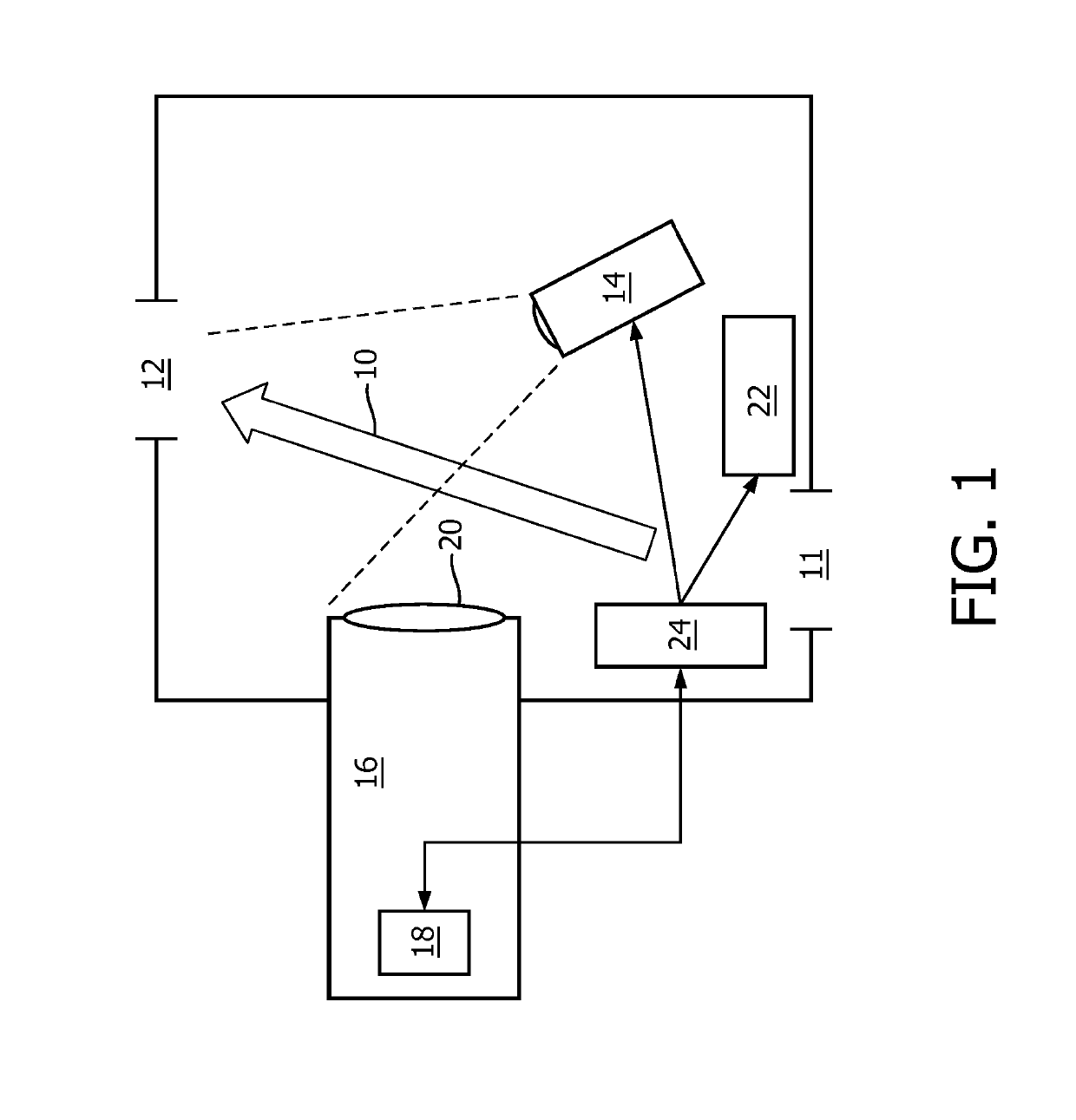
[0058]FIG. 1 shows an example of an optical sensor to which the invention may be applied. There is a gas flow 10 from an inlet 11 to an outlet 12 of the overall sensor device. An infrared LED 14 (λ=890 nm) is used to illuminate the gas flow to enable optical detection of entrained particles based on optical measurements of scattering. The LED is to one side of the detection vol...


PUM

PropertyMeasurementUnit
sizeaaaaaaaaaa
particle sizeaaaaaaaaaa
thresholdaaaaaaaaaa

Abstract

An optical particle sensor has at least first and second threshold settings applied to an optical sensor or a sensor signal to obtain first and second optical sensor readings. The first and second optical sensor readings are processed to determine a parameter which is dependent on a type of pollution event. The parameter is used to determine from at least one of the first and second optical sensor readings a mass of all particles below a first particle size. In this way the mass of all particles below a desired size can be evaluated, even though the optical sensor may not be responsive to the smallest particles.

Description

[0001]This application is the U.S. National Phase application under 35 U.S.C. § 371 of International Application No. PCT / EP2016 / 062815, filed on Jun. 6, 2016, which claims the benefit of International Application No. 15171916.8 filed on Jun. 12, 2015. These applications are hereby incorporated by reference herein.FIELD OF THE INVENTION[0002]This invention relates to optical particle sensors and sensing methods.BACKGROUND OF THE INVENTION[0003]Particle sensors are for example used to measure the level of pollution in the air.[0004]Low-cost systems are available based on the measurement of light scattered at the particles which pass along with an air flow through a detection volume in the sensor. This air flow is for example driven by a fan or a heater. Each particle is illuminated by a continuous light source and creates a light pulse with a duration determined by the passage time of the particle through the detection volume.[0005]These pulses are amplified, filtered and counted in a...

Claims


Application Information

Patent Timeline
Patent Type & Authority Patents(United States)
IPC IPC(8): G01N15/00G01N15/02G01N15/06G01N15/14G01N21/85G01N21/94
CPCG01N15/0205G01N15/06G01N15/1459G01N21/85G01N21/94G01N2021/8578G01N2015/025G01N2015/03G01N2015/1402
Inventor JONGERIUS, MICHIEL JOHANNESKOOIJMAN, GERBENKARAKAYA, KORAYOUWELTJES, OKKE
Owner KONINKLJIJKE PHILIPS NV
Why Eureka
Try Eureka