Modular fiber frame

a fiber frame and module technology, applied in the field of modules, can solve the problems of damage to fiber optic pigtails or fan outs, difficulty in obtaining new rights of way or permits, and inability to install a completely new optical fiber telecommunication network along with the existing coper network, and achieve the effect of increasing the connection density

Active Publication Date: 2019-07-30
CORNING RES & DEV CORP
View PDF16 Cites 6 Cited by
  • Summary
  • Abstract
  • Description
  • Claims
  • Application Information

AI Technical Summary

Benefits of technology

[0007]In a second embodiment, a modular fiber frame is disclosed. The modular fiber frame comprises a generally rectangular frame body having a front side and a back side and having a high density connection module integrally formed on apportion of the frame body, a splitter bracket configured to hold a plurality of optical splitter modules disposed on the front side of the frame body, wherein all connections to the plurality of optical splitter modules are made on the front side of the modular fiber frame, and a preterminated cable harness optically connected to connection ports on a back of the connection module, wherein the connection module includes a protective cover over said connection ports. In some embodiments, the exemplary modular fiber frame can utilize a second preterminated cable harness optically connected to a back of the connection module. In some embodiments, the exemplary modular fiber frame has a second connection module attached separately to the frame body to increase the connection density of the modular fiber frame.

Problems solved by technology

Installing a completely new optical fiber telecommunication network along beside of the existing coper network can be cost prohibitive due to space or aesthetic reasons.
Some service providers have a large embedded base of legacy copper networks that they would like to utilize to add fiber passive optical network (PON) splitter cabinets in densely populated cities or other areas where it is very difficult and time consuming to obtain new rights of way or permits from government or regulatory.
Adding fiber cables and pre-terminated harnesses into an existing copper cabinet risks the potential damage to the fiber optic pigtails or fan outs and also, if not protected, risks the potential to cause tight bends in the fibers that can lead to increased attenuation of the waveguide.

Method used


Image

  • Modular fiber frame
  • Modular fiber frame
  • Modular fiber frame

Examples


first embodiment

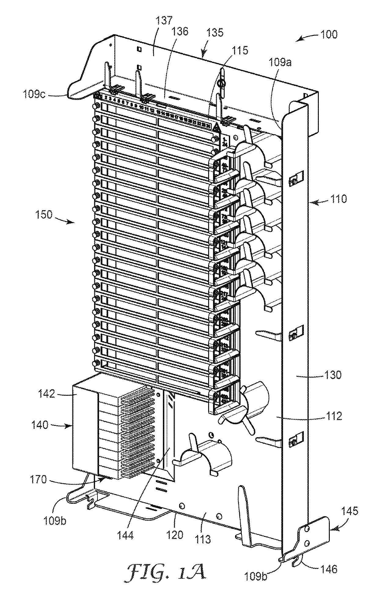
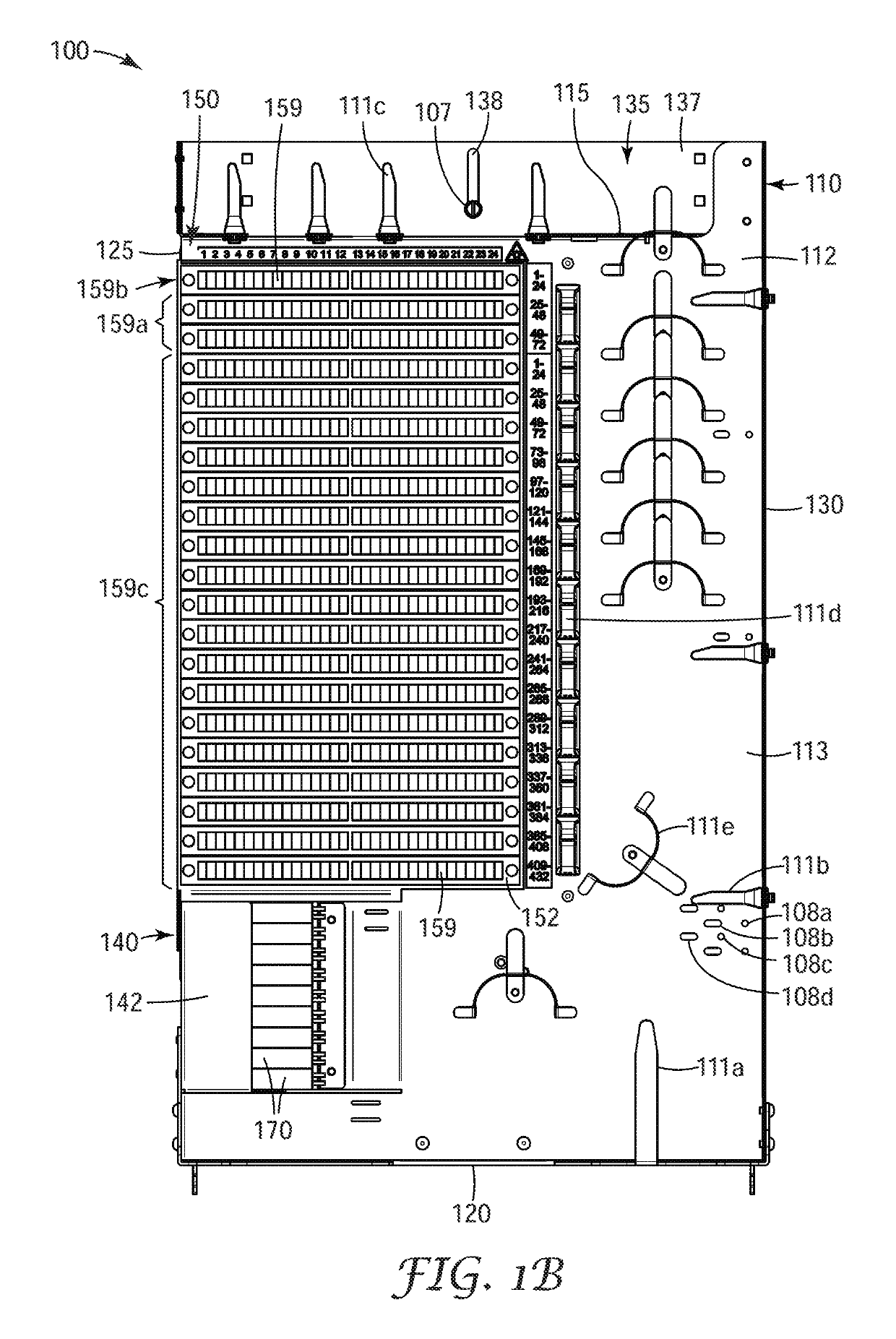
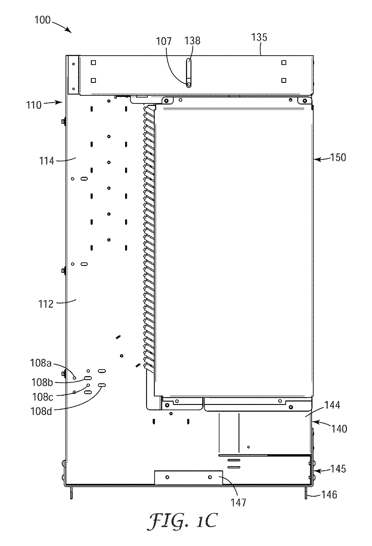
[0031]an exemplary modular fiber frame 100 is shown in FIGS. 1A-1E. Modular fiber frame 100 includes a frame body 110 and a connection module 150. The frame body comprises a flat face portion 112 has a generally rectangular shape having four edges: a top edge 115, a bottom edge 120, and two side edges 125, 130. The face portion has a front side (the first major surface) 113 and a back side 114 (the second major surface disposed opposite the first major or the front side). One or more of the edges can be bent so that it forms an L-shape with the face portion to provide structural support for the frame body as well as aiding in containing and protecting the optical fibers routed on the front side of the face portion. In the embodiment shown in FIG. 1A the second side edged 130 is bent so that it extends generally perpendicular to the face portion of the frame body.

[0032]Frame body 110 includes a splitter bracket 140 disposed adjacent to first edge 135 and below connection module 150. ...

second embodiment

[0071]FIG. 10 shows a modular fiber frame 200 having a distribution connection capacity of 288 with 24 feeder connections and 24 pass through connections and utilizes one 288 fiber cable harness and one 48 fiber cable harness split between the feeder and pass through connections. In this embodiment the optical splitter modules 270 have been moved to the right hand side of the frame body 210 and are oriented so that the splitter pigtails (not shown) exit the optical splitter module toward the bottom of the frame body.

[0072]The connection module in this embodiment includes 28 connection plates 252; each connection plate is configured to hold twelve SC optical fiber connector adapters 254. In an exemplary aspect, modular fiber frame 200 is configured to fit in a bay of a telecommunication cross-connect cabinet that is about 13 inches across the face of the bay, about 31 inches tall and less than 6 inches deep.

third embodiment

[0073]FIG. 11 shows a modular fiber frame 300 having a distribution connection capacity of 432 with 48 feeder connections and 48 pass through connections. The pass through connections 308 are located on the frame body rather than on the connection module. In this embodiment, the connection panel 350 includes 40 connection plates 352; each connection plate is configured to hold twelve SC optical fiber connector adapters (not shown). In an exemplary aspect, modular fiber frame 300 is configured to fit in a bay of a telecommunication cross-connect cabinet that is about 13 inches across the face of the bay, about 46 inches tall and less than 6 inches deep.

[0074]FIGS. 12A-12C are three views of a fourth exemplary modular fiber frame 400 illustrating the ability to configure the volume of the modular fiber frame to function in multiple applications. FIG. 12A shows the frame body 410 with a first connection module 450 mounted on the upper half of the frame body, an opening 419 for mounting...


PUM


Abstract

A modular fiber frame is disclosed that comprises a generally rectangular frame body, a high density connection module attached to a front side of the frame body, a splitter bracket to hold a plurality of optical splitter modules on the front side of the frame body. All of the splitter connections can be made on the front side of the modular fiber frame, and a preterminated cable harness optically connected to connection ports on a back of the connection module, wherein the connection module includes a protective cover over said connection ports. In some embodiments, the exemplary modular fiber frame can utilize a second preterminated cable harness optically connected to a back of the connection module.

Description

FIELD OF THE INVENTION[0001]The present invention relates to a modular fiber frame having a high density connection module. In particular, the exemplary modular fiber frame is configured to retrofit an existing telecommunication cabinet to provide high speed data connections.BACKGROUND OF THE INVENTION[0002]Telecommunication network designs vary depending on the terrain, the density of the population, existing infrastructure, and other factors. Optical fiber networks in fiber to the end user networks and in the backbone for wireless networks, such as fiber to the antenna (FTTA) networks, are displacing conventional digital subscriber line or DSL copper networks. Installing a completely new optical fiber telecommunication network along beside of the existing coper network can be cost prohibitive due to space or aesthetic reasons. Therefore, network providers are seeking to take advantage of previously acquired rights of way, city pad permitting, cable conduits, vaults, etc. by replac...

Claims


Application Information

Patent Timeline
Patent Type & Authority Patents(United States)
IPC IPC(8): G02B6/00G02B6/44
CPCG02B6/4454G02B6/4452G02B6/44524G02B6/44528
Inventor THOMPSON, ZACHARY M.HAGGAR, JONATHAN V.BORER, VICTOR J.MERTZ, ROBERT R.KROZEL, ADAM J.
Owner CORNING RES & DEV CORP
Why Eureka
Try Eureka