
Image correction design system and method for oral and maxillofacial surgery

a design system and technology for applied in the field of image correction design system and method for can solve the problems of prolonging the surgery time, misjudgment of the surgery portion, and inaccurate image data of the photographic equipment used in oral and maxillofacial surgery, so as to achieve the effect of reducing the time for performing dental, orthognathic and facial plastic surgery

Active Publication Date: 2019-08-13
SHE CHENG XIN
View PDF12 Cites 0 Cited by
  • Summary
  • Abstract
  • Description
  • Claims
  • Application Information

AI Technical Summary

Benefits of technology

[0013]The main purpose of the invention is to provide an image correction design method for an oral and maxillofacial surgery. The method can be used in dental, orthognathic and facial plastic surgery. According to an image correction design method for an oral and maxillofacial surgery of the invention, since a process of correction and comparison of scanning images is executed, the time for performing the dental, orthognathic and facial plastic surgery can be shortened, and the features of human skeleton of surgery is simulated to position the skeleton and a correction appliance accurately and combine firmly after surgery.
[0014]Another main purpose of the invention is to provide an image correction design system for an oral and maxillofacial surgery, wherein a scanning image correction and comparison module is used for correcting and comparing the image data from the first image data scanning module and the image data from the second image data scanning module so that the image correction design system for an oral and maxillofacial surgery can have effect of accurately positioning an operation site before surgery and accurately positioning a fixing plate combining with the skeleton after surgery.
[0024]Preferably, the step of a surgery guiding bone plate correction provides a correction for surgery cutting area and an accurate position correction of a surgery guiding bone plate.
[0025]Preferably, the step of a fixing bone plate correction provides an accurate position of a fixing bone plate for skeleton healing over after surgery and the correction for the determined position of the skeleton.
[0037]Preferably, the surgery guiding bone plate correction module provides a correction for surgery cutting area and a position correction for accurately drilling holes on a surgery guiding bone plate.
[0038]Preferably, the fixing bone plate correction module provides an accurate position of a fixing bone plate for skeleton healing over after surgery and a correction for the determined position of the skeleton.

Problems solved by technology

However, the common medical photographic equipment used in an oral and maxillofacial surgery cannot provide a correct image data accurately for simulation assessment before surgery or healing over confirmation after surgery to a physician.
The photographs are not true to the original that may cause misjudgment of the surgery portion and a prolongation of surgery time.
Also, it fails to provide a physician with a comparing basis for tracking healing and preoperative assessment in real time during corrective treatment after surgery.
In addition, it is possible to cause disadvantages of malocclusion that a patient fails to have a correct occlusion or has an excessive occlusion.
However, the planning and prediction method for optimizing facial skeleton symmetry fails to solve the problem that image is affected by noise and other interference factors, so that the converted file is not true to the original or the image is vague to cause misjudgment, and thus it cannot provide a correct image data accurately for simulation assessment before surgery or healing over confirmation after surgery by a physician.
However, the above method still has accuracy problem of the CT images and patient's jaw models.
It's possible to cause disadvantages of malocclusion that a patient fails to have a correct occlusion or has an excessive occlusion.
However, the above method cannot scan the skeleton image accurately and provide positioning, and thus it cannot provide a correct image data accurately for simulation assessment before surgery or healing over confirmation after surgery by a physician.

Method used


Image

  • Image correction design system and method for oral and maxillofacial surgery
  • Image correction design system and method for oral and maxillofacial surgery
  • Image correction design system and method for oral and maxillofacial surgery

Examples


first embodiment

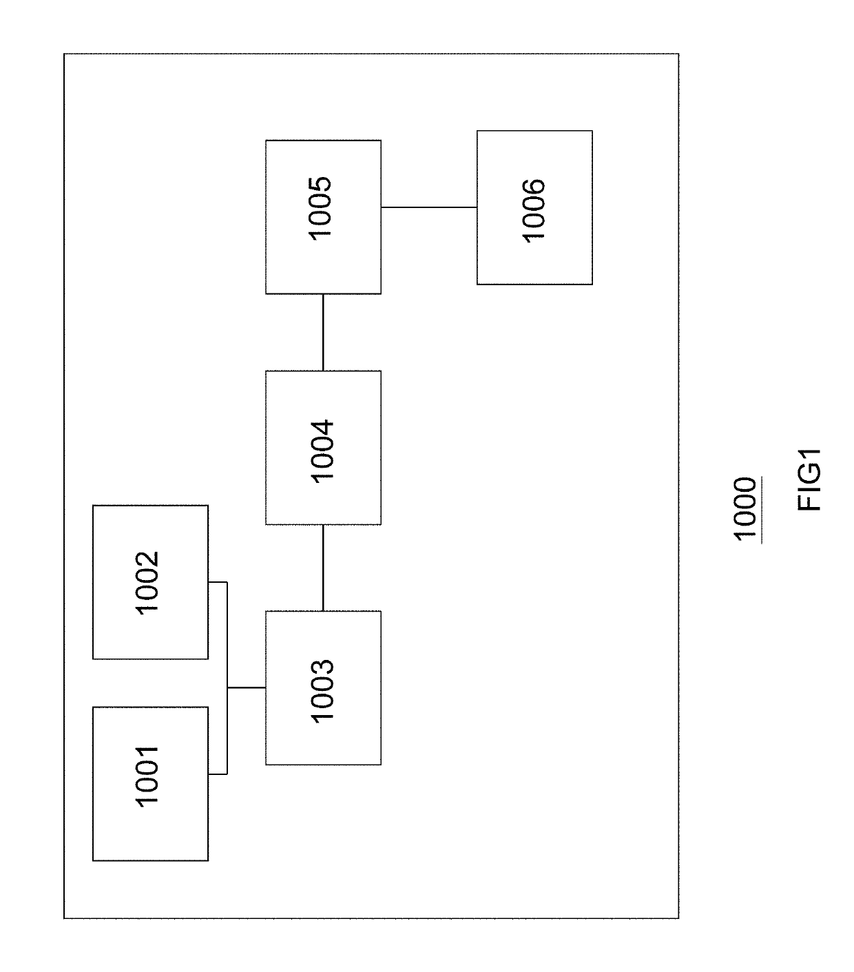
[0062]FIG. 1 shows a functional block diagram of an image correction design system for an oral and maxillofacial surgery of the invention, wherein the image correction design system for an oral and maxillofacial surgery 1000 comprises: a first image data scanning module 1001; a second image data scanning module 1002; a scanning image correction and comparison module 1003; an image block calculation module 1004; a surgery simulation image design module 1005; and an output module 1006.

second embodiment

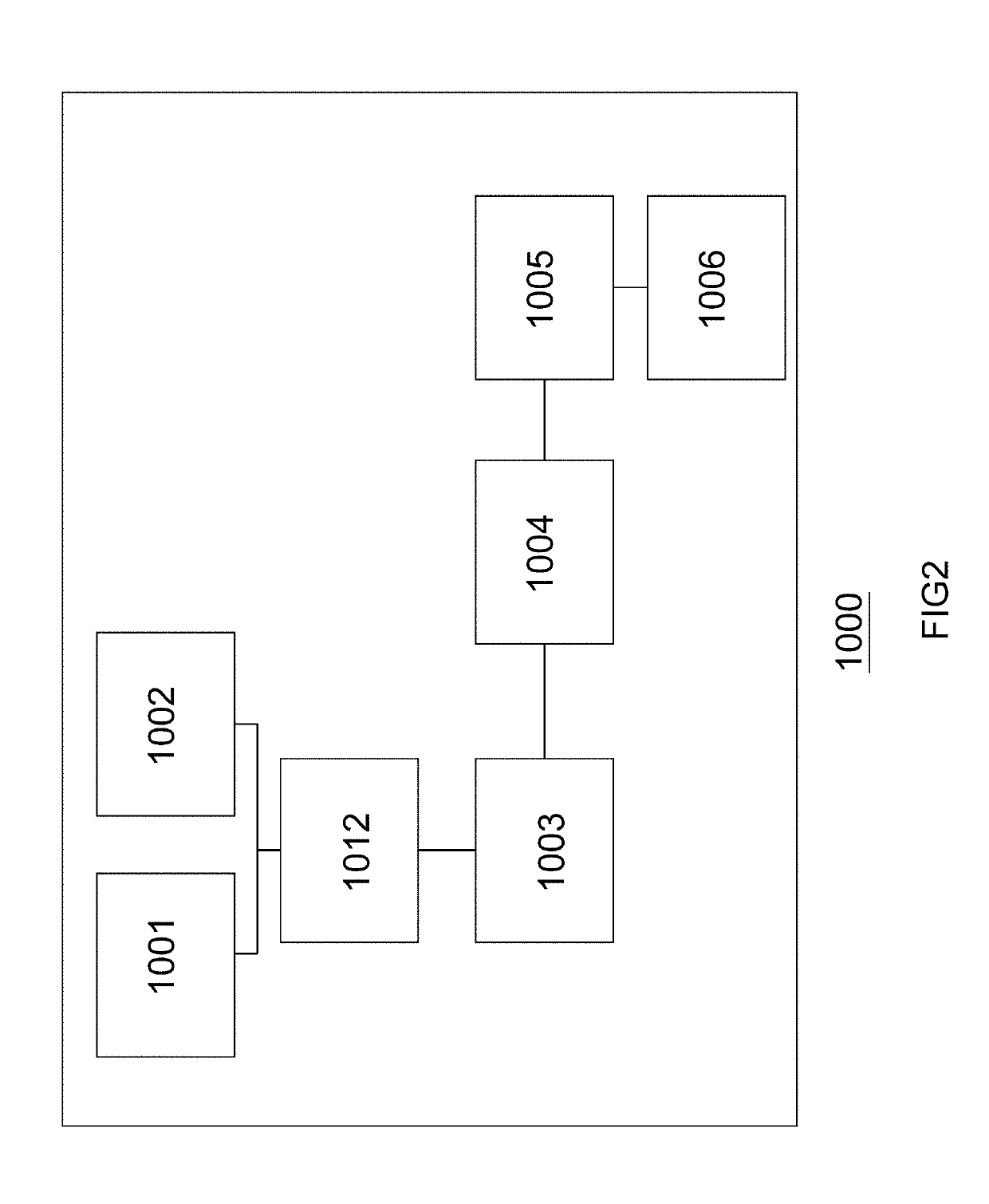
[0063]FIG. 2 shows a functional block diagram of an image correction design system for an oral and maxillofacial surgery of the invention. When an orthognathic surgery is performed by a physician, a clinic file of X-ray machine or computerized tomography (CT) scan is needed to confirm a predetermined operation site. An image correction design system for an oral and maxillofacial surgery 1000 can provide a correct and accurate image to a physician for reference. When an image correction design system for an oral and maxillofacial surgery 1000 is performed, starting the first image data scanning module 1001 is executed. The first image data scanning module 1001 is used for scanning to obtain image data of relative coordinate positions of maxillofacial bones, teeth, and soft tissues of a patient, wherein the first scanning image data is an image taken by X-ray machine or computerized tomography scan equipment, and the image is like a computerized tomography scan file (hereafter referre...

third embodiment

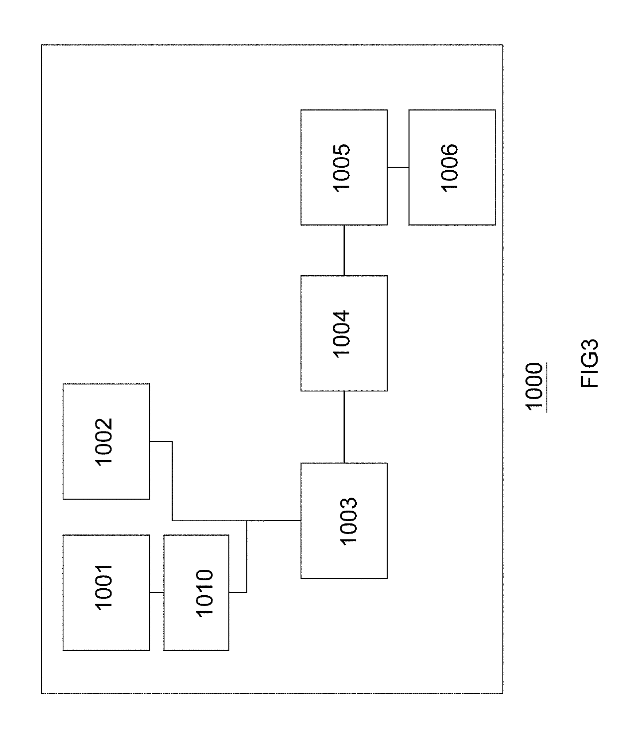
[0067]FIG. 3 shows a functional block diagram of an image correction design system for an oral and maxillofacial surgery of the invention, wherein the image correction design system for an oral and maxillofacial surgery 1000 comprises: a first image data scanning module 1001; an image data conversion module 1010; a second image data scanning module 1002; a scanning image correction and comparison module 1003; an image block calculation module 1004; a surgery simulation image design module 1005; and an output module 1006.

[0068]Following the above-mentioned third embodiment, for an image correction design system for an oral and maxillofacial surgery 1000, a first image data scanning module 1001 further comprises an image data conversion module 1010 for converting the first scanning image data such as Dicom file including bones, teeth and soft tissues that is stored in the first image data scanning module 1001 to a 3 dimension (3D) data file, wherein the format of the 3 dimension (3D) ...


PUM


Abstract

An image correction design system for an oral and maxillofacial surgery. The image correction design system comprises: a first image data scanning module for scanning to obtain image data of relative coordinate positions of maxillofacial bones, teeth, and soft tissues; a second image data scanning module for scanning image data of a plaster dental impression of a patient; a scanning image correction and comparison module for correcting and comparing the image data from the first image data scanning module and the image data from the second image data scanning module and performing archiving to obtain first archives; an image block calculation module for performing an image layer management and block cutting display of the first archives to obtain second archives; a surgery simulation image design module for inputting a surgery data parameter for the second archives after the image layer management and cut block display, so as to design and establish surgery simulation image files; and an output module for outputting the surgery simulation image files by using a display device.

Description

CROSS REFERENCE OF RELATED APPLICATION[0001]This is a U.S. National Stage under 35 U.S.C. 371 of the International Application Number PCT / CN2015 / 081083, filed Jun. 9, 2015. The afore-mentioned patent application is hereby incorporated by reference in its entirety.NOTICE OF COPYRIGHT[0002]A portion of the disclosure of this patent document contains material which is subject to copyright protection. The copyright owner has no objection to any reproduction by anyone of the patent disclosure, as it appears in the United States Patent and Trademark Office patent files or records, but otherwise reserves all copyright rights whatsoever.BACKGROUND OF THE PRESENT INVENTION[0003]Field of Invention[0004]This invention generally relates to an image correction design system and method for an oral and maxillofacial surgery, especially to an image correction design system and method for a dental, orthognathic and facial plastic surgery.[0005]Description of Related Arts[0006]Orthognathic surgery is...

Claims


Application Information

Patent Timeline
Patent Type & Authority Patents(United States)
IPC IPC(8): G16H30/40A61B6/14A61B34/10G16H20/40G16H50/50G06T7/00G06T5/00G06K9/62
CPCA61B34/10A61B6/14G06K9/6202G06T5/002G06T7/0014G16H20/40G16H50/50G16H30/40G06T2207/30036A61B2034/104A61B2034/105G06T2200/04G06T2207/10081
Inventor SHE, CHENG XIN
Owner SHE CHENG XIN
Learn More