Engine assembly of an aircraft including a display unit

a technology of display unit and engine, which is applied in the direction of mobile visual advertising, combustion air/fuel air treatment, instruments, etc., can solve the problems of difficult implementation of arrangement, and achieve the effect of avoiding any disturbance of flow

Active Publication Date: 2019-08-13
AIRBUS OPERATIONS (SAS)
View PDF23 Cites 0 Cited by
  • Summary
  • Abstract
  • Description
  • Claims
  • Application Information

AI Technical Summary

Benefits of technology

[0011]Thus, thanks on one hand to the embodiment of the display unit in the form of light rings arranged in the air intake, which makes it possible to generate, in an effective manner, a display on the blades of the fan, and thanks on the other to the integration of light rings inside the air intake of the pod, which makes it possible to avoid any disturbance of flow, an optimum embodiment and an optimum arrangement of the display unit are obtained.

Problems solved by technology

Such an embodiment and such an arrangement are not easy to implement, notably to be effective and optimum relative to the envisaged utilization.

Method used


Image

  • Engine assembly of an aircraft including a display unit
  • Engine assembly of an aircraft including a display unit
  • Engine assembly of an aircraft including a display unit

Examples


first embodiment

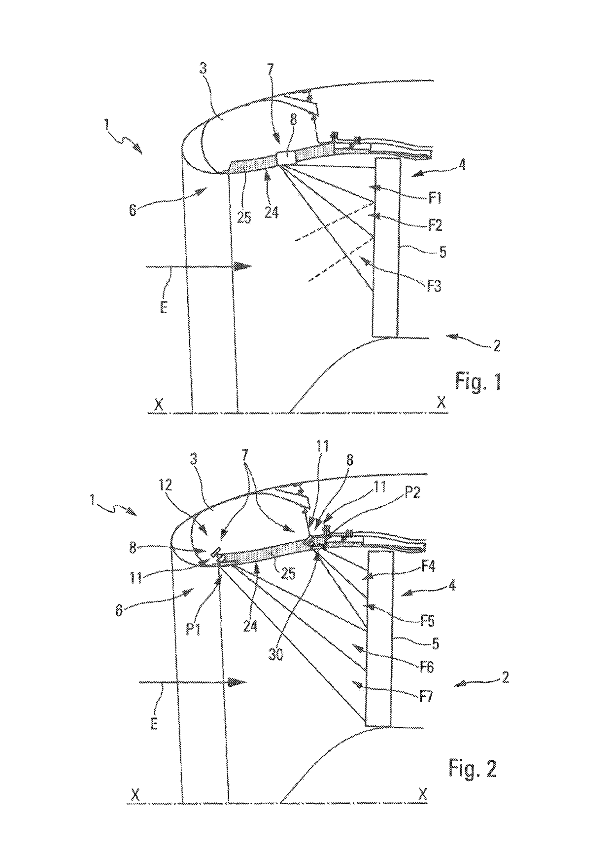
[0068]In a first embodiment, illustrated on FIG. 1, the display unit 7 includes a single light ring 8 (represented very schematically), which is arranged in an acoustic panel 25 of the air intake 6. The acoustic panel is formed, in a conventional manner, to reduce the noise generated by the engine 2.

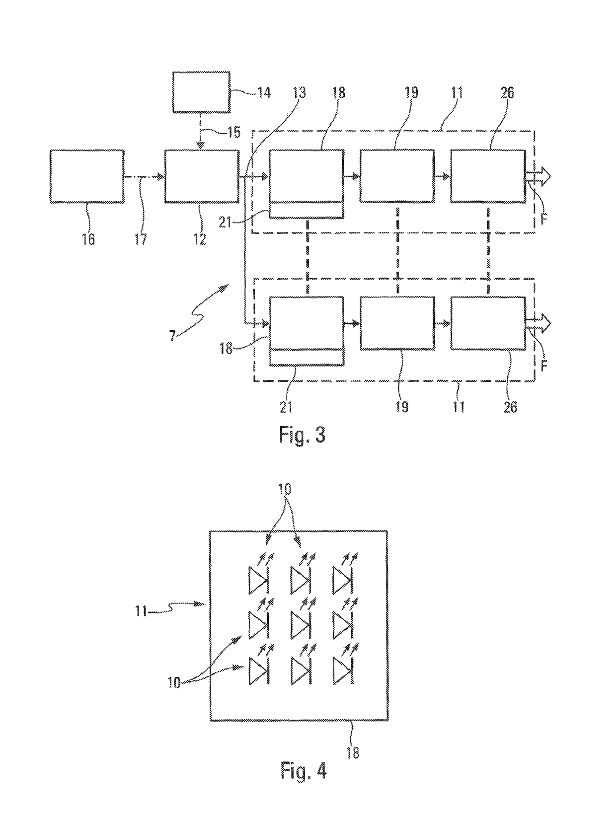
[0069]As an illustration, in the embodiment of FIG. 1, each optical unit of the display unit 7 can comprise 9 light-emitting diodes. These diodes, 774 in this case, are mounted on 86 optical units with 3 different longitudinal positions (along the direction defined by the axis X-X). Three light beams F1 to F3 are emitted by the light ring 8, respectively from these three longitudinal positions. In this example, the light ring 8 can comprise, as an illustration:[0070]41 optical units for generating the beam F1, which is radially the outermost on the fan 4 in relation to the axis X-X;[0071]29 optical units for generating the central beam F2; and[0072]16 optical units for generating the bea...

second embodiment

[0073]Moreover, in a second embodiment, illustrated on FIG. 2, the display unit 7 includes two light rings 8, arranged, respectively upstream and towards downstream of the acoustic panel 25 of the air intake 6.

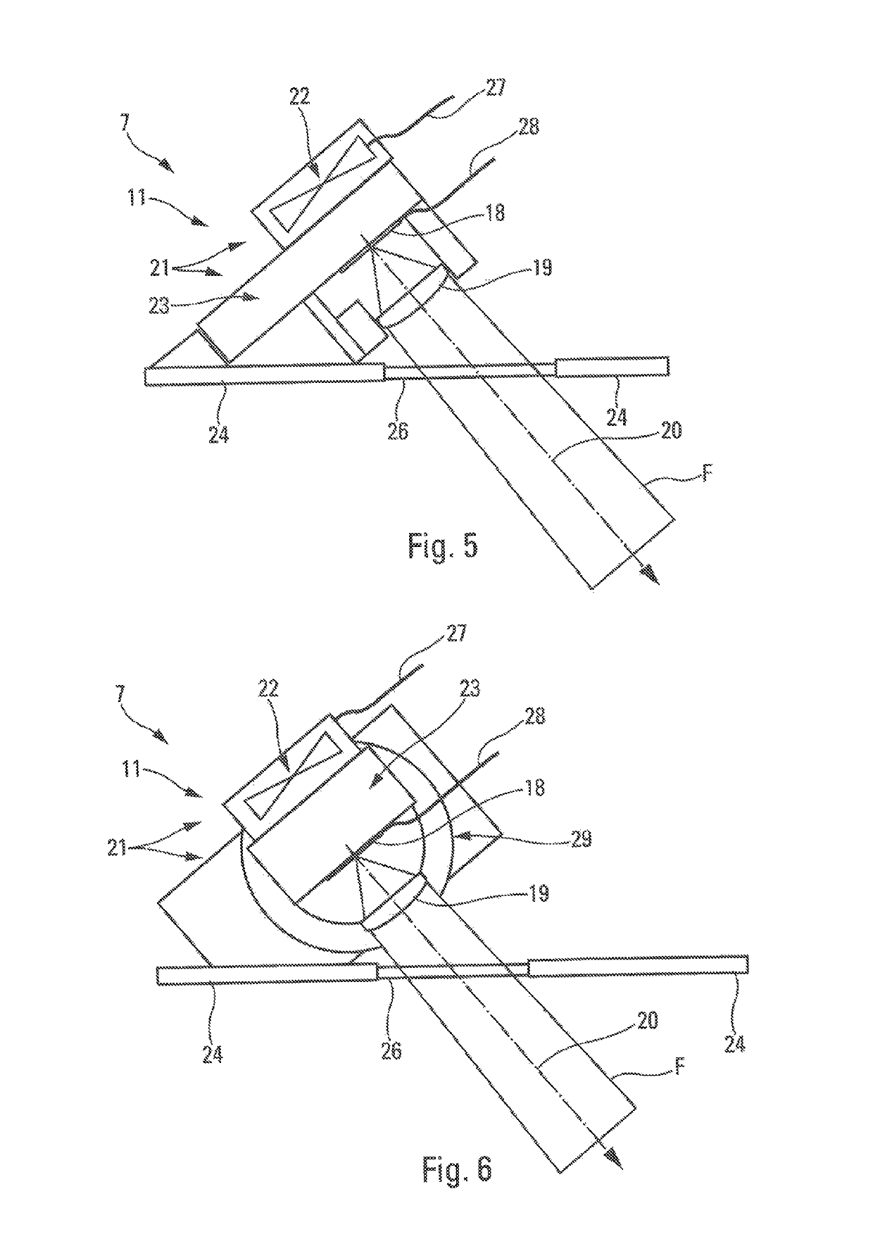
[0074]A first light ring 8 is positioned at the upstream extremity P1 of the acoustic panel 25. This first light ring 8 is represented on FIG. 2 through an optical unit 11 similar to that of FIG. 5.

[0075]The second light ring is positioned at a position P2 towards the downstream extremity of the acoustic panel 25, in this latter. In this example, the light ring 8 (at position P2) is also represented through an optical unit 11 similar to that of FIG. 5.

[0076]Furthermore, as an illustration, in this embodiment of FIG. 2, each optical unit 11 can comprise 9 light-emitting diodes. These diodes, 918 in this case, are mounted on 102 optical units at 4 different longitudinal positions (along the direction defined by the axis X-X).

[0077]If each longitudinal position includes three row...


PUM


Abstract

An engine assembly comprising an engine and a pod surrounding the engine that is equipped, upstream according to the direction of entry of air into the engine, with a fan provided with blades, the pod having an upstream air intake. The engine assembly also comprises a display unit including at least one light ring arranged in the air intake upstream of the fan, the light ring including at least one row of light-emitting diodes and being configured to emit at least one light beam and to project it on the blades of the fan.

Description

CROSS-REFERENCES TO RELATED APPLICATIONS[0001]This application claims the benefit of the French patent application No. 1555115 filed on Jun. 5, 2015, the entire disclosures of which are incorporated herein by way of reference.BACKGROUND OF THE INVENTION[0002]This invention relates to an engine assembly of an aircraft including a display unit, the engine assembly comprising an engine and a pod surrounding the engine.[0003]A device is known through document FR-3 002 360 for displaying images on an outside part of a mobile vehicle, and notably an aircraft. This display device comprises at least one laser source, which is capable of generating a light, spatially and temporally coherent, and which is configured to project at least one dynamic image on an outside part of the mobile vehicle, in particular on the fuselage of an aircraft or on the air intake of an engine of the aircraft. In the case of a display on an engine, the laser source is planned to be arranged on the fuselage, near t...

Claims


Application Information

Patent Timeline
Patent Type & Authority Patents(United States)
IPC IPC(8): B64D27/10G09F21/10G09F19/18B64D47/00F01D25/24F04D29/38F02C7/04F04D27/00F04D29/32F21W107/30
CPCB64D47/00B64D27/10F01D25/24F02C7/04F04D29/325F04D29/38G09F19/18G09F21/10F04D27/001F05D2220/323A01M29/10B64D33/02B64D47/02B64D2045/0095B64D2033/022A01M29/06
Inventor PORTE, ALAINCHELIN, FREDERICREHM, WOLFGANGPAPIN, NATHALIEMORENO GONZALEZ, IRENE
Owner AIRBUS OPERATIONS (SAS)
Why Eureka
Try Eureka