Tool cathode and clamping method for electrolytic machining of special-shaped cavity

A tool cathode and special-shaped technology, which is applied in the direction of electrochemical processing equipment, manufacturing tools, metal processing equipment, etc., can solve the problems of inability to adapt to small batches or single-trial electrolytic processing of workpieces, and low efficiency, so as to facilitate observation of the processing process, The effect of improving work efficiency and uniform flow field diffusion

Active Publication Date: 2021-08-03
CHENGDU AIRCRAFT INDUSTRY GROUP +1
View PDF7 Cites 0 Cited by
  • Summary
  • Abstract
  • Description
  • Claims
  • Application Information

AI Technical Summary

Problems solved by technology

Although the above-mentioned patent avoids the design and manufacture of the external liquid supply nozzle and its related fixtures, reduces the complexity and cost of the process, and ensures the dimensional accuracy and surface quality of the electrolytic turning repair, but if the above-mentioned device is intended to be used for various axes The electrolytic turning repair of similar parts still needs to disassemble the tool cathode, which cannot adapt to the electrolytic machining of small batches or single-trial workpieces, and the efficiency is low

Method used


Image

  • Tool cathode and clamping method for electrolytic machining of special-shaped cavity
  • Tool cathode and clamping method for electrolytic machining of special-shaped cavity
  • Tool cathode and clamping method for electrolytic machining of special-shaped cavity

Examples


Embodiment 1

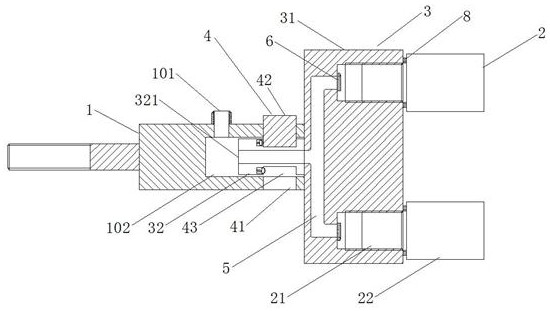
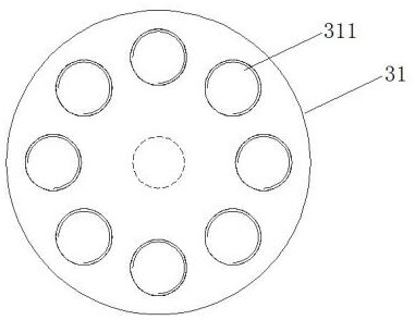
[0035] This embodiment discloses a tool cathode for electrolytic machining of a special-shaped cavity, including a cathode rod 1 and a cathode 2, a first liquid inlet 101 is provided on the cathode rod 1, a blind hole 102 is provided in the center of the cathode rod 1, and a combined cathode Disk 3, the combined cathode disk 3 includes a disk 31 and a cylindrical rod 32, the cylindrical rod 32 extends into the blind hole 102 and can rotate in the blind hole 102, the cylindrical rod 32 is connected to the cathode rod 1 through the key connection mechanism 4, The interior of the disc 31 and the cylindrical rod 32 are connected in hollow to form an electrolyte channel 5, and one end of the cylindrical rod 32 extending into the blind hole 102 is provided with a second liquid inlet 321, and the surface of the disc 31 is provided with several threaded holes 311 connected with the cathode 2 , The threaded hole 311 communicates with the electrolyte channel 5, and the threaded hole 311 ...

Embodiment 2

[0038]This embodiment discloses a tool cathode for electrolytic machining of a special-shaped cavity, including a cathode rod 1 and a cathode 2, a first liquid inlet 101 is provided on the cathode rod 1, a blind hole 102 is provided in the center of the cathode rod 1, and a combined cathode Disk 3, the combined cathode disk 3 includes a disk 31 and a cylindrical rod 32, the cylindrical rod 32 extends into the blind hole 102 and can rotate in the blind hole 102, the cylindrical rod 32 is connected to the cathode rod 1 through the key connection mechanism 4, The interior of the disc 31 and the cylindrical rod 32 are connected in hollow to form an electrolyte channel 5, and one end of the cylindrical rod 32 extending into the blind hole 102 is provided with a second liquid inlet 321, and the surface of the disc 31 is provided with several threaded holes 311 connected with the cathode 2 , The threaded hole 311 communicates with the electrolyte channel 5, and the threaded hole 311 i...

Embodiment 3

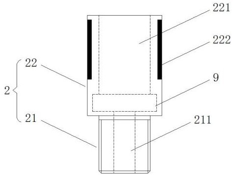
[0049] This embodiment discloses a method for clamping the cathode of a tool for electrolytic machining of a special-shaped cavity. The cathode rod 1 is connected to the spindle 10 of the machine tool through the cathode rod thread, and the cylindrical rod 32 of the combined cathode disc 3 extends into the blind hole 102 of the cathode rod 1. In this process, the key connection mechanism 4 is connected to the cathode rod 1, and the threaded part 21 of the cathode 2 is installed in the threaded hole 311 of the disc 31, and the cathode part 22 enters the transparent acrylic reaction back pressure cavity 11, and the transparent acrylic reaction back pressure Both the cavity 11 and the workpiece 12 to be processed are installed on the workpiece holder 13, and are positioned and clamped by threads.

[0050] The cathode is placed in a transparent reaction back pressure chamber for electrolytic processing, which is convenient for observing the processing process. At the same time, the...


PUM


Abstract

This application relates to an electrochemical processing device, and discloses a tool cathode for electrolytic processing of a special-shaped cavity and a clamping method, including a cathode rod and a cathode, the cathode rod is provided with a first liquid inlet, and the center of the cathode rod is provided with a blind hole. Including a combined cathode disk, the combined cathode disk includes a disc and a cylindrical rod, the cylindrical rod extends into the blind hole and can rotate in the blind hole, the cylindrical rod is connected with the cathode rod through a key connection mechanism, and the interior of the disc and cylindrical rod is hollow Connected to form an electrolyte channel, the end of the cylindrical rod extending into the blind hole is provided with a second liquid inlet, the surface of the disc is provided with a number of threaded holes connected to the cathode, the threaded holes communicate with the electrolyte channel, and the threaded hole is provided with a rotary seal piece, the rotary closure piece is connected with the control part. The design of the combined cathode plate of the present application can quickly select the cathode required for a single processing, which improves work efficiency and reduces production costs, and is suitable for one-time electrolytic processing of small batches or single-trial workpieces.

Description

technical field [0001] The invention relates to an electrochemical machining device, in particular to a tool cathode for electrolytic machining of a special-shaped cavity and a clamping method. Background technique [0002] For workpieces with conventional shapes such as round and square structures, low-cost, high-efficiency, and high-precision components can be obtained through traditional processing methods, but it is more difficult for irregular shapes such as special-shaped holes and special-shaped cavities. Traditional machining methods, for special-shaped cavities, especially thin-walled ones, when milling is used, the residual stress is likely to cause micro-deformation of the structure, resulting in a large shape and position error; for special-shaped holes, traditional drills cannot achieve holes The shape requirements of the machining, and the difficulty of chip removal and severe heat generation during the drilling process cannot be used as an ideal processing met...

Claims


Application Information

Patent Timeline
Patent Type & Authority Patents(China)
IPC IPC(8): B23H3/00
Inventor 余泽刘巍左敦稳李国华何亚峰卢文壮张鹏
Owner CHENGDU AIRCRAFT INDUSTRY GROUP
Why Eureka
Try Eureka