Tape measuring device

a tape measuring and tape measure technology, applied in the field of tape measuring devices, can solve the problems of not providing highly accurate sighting of dimensions measured by pocket or hand-held tape measures, not retaining accurate measurements, and common precision and efficiency, so as to facilitate the transfer and marking of such measurements, facilitate the quick and easy manipulation of tape measures, and duplicate multiple pieces of work

Inactive Publication Date: 2019-08-13
M1 ENTERPRISES LLC
View PDF58 Cites 0 Cited by
  • Summary
  • Abstract
  • Description
  • Claims
  • Application Information

AI Technical Summary

Benefits of technology

[0004]The tape measuring device includes an indicator and marking assembly that improves the accuracy and replication of a measurement. The indicator and marking assembly includes a mount that may be removably or integrally attached to a housing of the tape measure. The indicator and marking assembly further comprises a stop plate disposed on the mount. The stop plate comprises a main frame having a front wall oppositely situated to a back wall, wherein the back wall physically abuts the mount. A cutout is formed through the front and back walls of the stop plate to create a pair of oppositely situated flanges. The front walls of the flanges are coplanar with the front wall of the main frame of the stop plate.
[0005]The mount is positioned on the housing of the marking device such that a top side of the mount is adjacent to a front wall of the housing, wherein a tape blade of the measuring device extends through an aperture formed through the front wall and through an opening formed through a front wall of the mount. The flanges of the stop plate are arranged such that the tape blade extends between the flanges, and the flanges are directed towards the tape blade so that the flanges may assist in the reading of the measuring indicia on the tape blade. A front wall of the stop plate is contiguously formed with the front walls of the flanges, and is coplanar therewith.
[0007]The small size of the device allows a user to readily hold and manipulate the tape measure. A user can take accurate measurements in positions of poor visibility and awkward accessibility. A user can set precise measurements taken from other media or instructions, and lock such precise measurements in place on the tape measure. A user can easily transfer and mark such measurements onto another piece of work, and / or duplicate multiple pieces of work.
[0008]The present invention, when used, e.g., as an attachment to or part of a standard pocket tape measure, eliminates the problems of inaccurate human eyesight and memory, and eliminates the need to manipulate a separate marking tool, pen or pencil for recording, transferring and marking precise measurements. It solves the problems of poor accuracy, inefficiency, wasted time and material. The present measuring and marking device further facilitates precise measurement taking and reading for those persons who otherwise cannot read numbers readily, such as those suffering from dyslexia, weak eyesight, poor motor skills, etc.
[0009]The tape measuring device may further include a housing that is specially designed and configured to better withstand breakage and damage. This is largely a result of the formation of a plurality of cuts within the two side walls of the housing of the tape measuring device. The tape measuring device further reduces the changes of damages by placing an optional locking mechanism in a recessed position relative to the housing of the device. Furthermore, components of the marker plate are sized and dimensioned to be recessed relative to the housing of the tape measuring device, thereby minimizing their exposure to damage.

Problems solved by technology

Precision and efficiency are common problems in reading, recording, transferring and marking of measurements.
Standard “pocket” or hand-held tape measures do not provide highly accurate sighting of the dimensions measured, do not retain the accurate measurement for transfer to another location or material piece of work, and do not include a tool to accurately scribe or mark the measurement immediately after transfer.
Also, currently known tape measuring devices are susceptible to breakage and damage due to inferior construction and design.

Method used


Image

  • Tape measuring device
  • Tape measuring device
  • Tape measuring device

Examples


Embodiment Construction

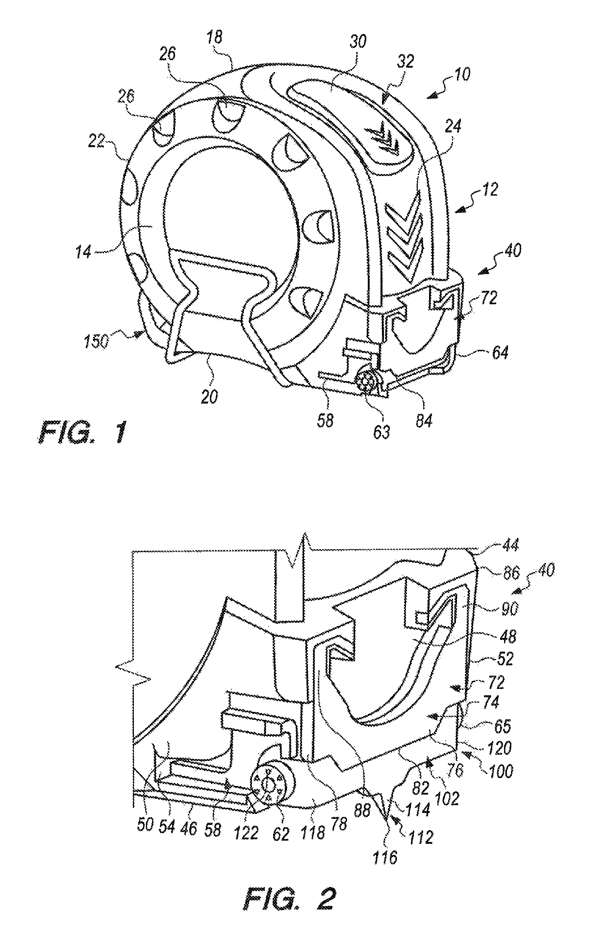
[0023]The improved tape measuring device of the present invention comprises an indicator and marking assembly comprising a mount, a stop plate, and a marker plate. The mount is specially configured to be integrally formed with or easily attached to a standard tape measure including, for example, a standard size / shape of “pocket” or hand-held tape measure, thereby enhancing normal usage and function of the tape measure. Alternatively, the mount may be integrally formed with or easily attached to an exemplary housing for a tape measure as shall be described herein. Each of the stop plate and the marker plate is configured and positioned relative to one another on the mount to provide a reliable way of measuring, tracking, and replicating a measurement. More particularly, the stop element provides a means whereby a tape blade of the tape measuring device, may be stabilized temporarily without the necessity of implementing a locking mechanism such as is typically found in conventional t...


PUM


Abstract

A tape measuring device comprising a mount which is integrally formed with or attached to a housing. A specially designed stop plate is disposed on the mount. The stop plate provides a means whereby the indicia located on a tape blade of the tape measuring device may be easily located and read. The stop plate further provides a means for the precise taking and replication of a measurement. The tape measuring device further comprises a marker plate. The marker plate comprises a scribe which can mark an object to be measured. The marker plate is pivotally attached to the mount to allow for the retraction of the scribe when the marker plate is not in use, and for expansion of the scribe when the marker plate is in use.

Description

BACKGROUND TO THE INVENTION1. Field of the Invention[0001]The present invention relates to measuring devices, and more particularly, to a device for measuring, reading, transferring, and marking a measurement to be marked on a piece of work or material.2. Background of the Invention[0002]Precision and efficiency are common problems in reading, recording, transferring and marking of measurements. Standard “pocket” or hand-held tape measures do not provide highly accurate sighting of the dimensions measured, do not retain the accurate measurement for transfer to another location or material piece of work, and do not include a tool to accurately scribe or mark the measurement immediately after transfer. Also, currently known tape measuring devices are susceptible to breakage and damage due to inferior construction and design.SUMMARY OF THE INVENTION[0003]The above-mentioned problems of the prior art are overcome or eliminated by a measuring and marking device for use in the precise tak...

Claims


Application Information

Patent Timeline
Patent Type & Authority Patents(United States)
IPC IPC(8): G01B3/10
CPCG01B3/1084G01B3/1061G01B3/1056G01B2003/1089G01B3/1089
Inventor PERI, ODED
Owner M1 ENTERPRISES LLC
Why Eureka
Try Eureka