Optical driver apparatus, optical apparatus and image capturing apparatus

a technology of optical devices and driver devices, applied in the field of optical driver devices, can solve problems such as excessive actuator load

Active Publication Date: 2019-08-13
CANON KK
View PDF13 Cites 0 Cited by
  • Summary
  • Abstract
  • Description
  • Claims
  • Application Information

AI Technical Summary

Benefits of technology

[0008]The present invention provides an optical driver apparatus capable of avoiding, when an optical apparatus having a locking mechanism for restraining motion of an operation member, a generation of an excessive load in an actuator and a transmission mechanism for driving the operation member. The present invention further provides an optical apparatus and an image capturing apparatus to which the optical driver apparatus is attachable.

Problems solved by technology

However, if the optical apparatus to which the optical driver apparatus is attached has a locking mechanism for locking (restraining) motion of the operation member, driving the actuator of the optical driver apparatus when the locking mechanism is in a locking state generates an excessive load in the actuator and in a transmission mechanism (gears or the like) for transmitting a driving force from the actuator to the operation member.

Method used


Image

  • Optical driver apparatus, optical apparatus and image capturing apparatus
  • Optical driver apparatus, optical apparatus and image capturing apparatus
  • Optical driver apparatus, optical apparatus and image capturing apparatus

Examples


embodiment 1

[Embodiment 1]

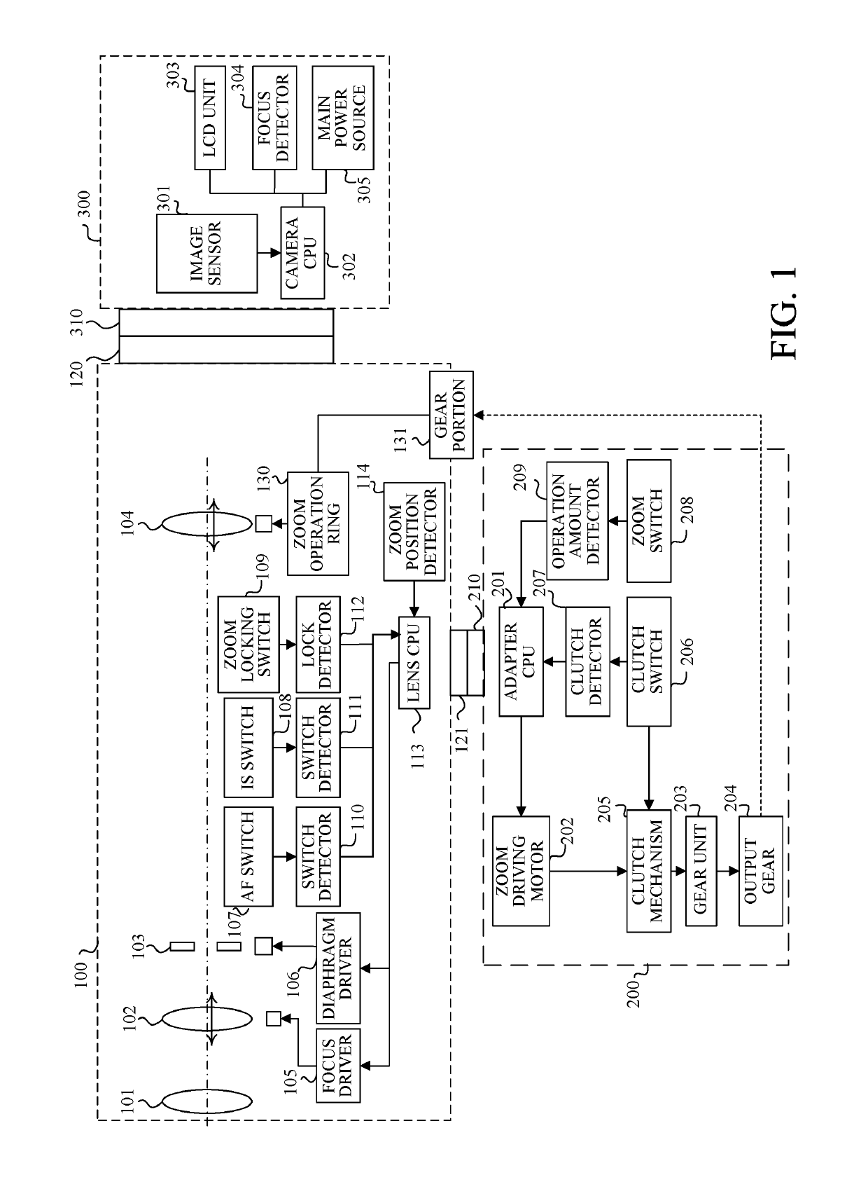
[0018]FIG. 1 illustrates a driving adapter 200 as an optical driver apparatus that is a first embodiment (Embodiment 1) of the present invention. The driving adapter 200 is hereinafter simply referred to as “an adapter 200”. The adapter 200 is detachably attachable to a lens barrel of an interchangeable lens 100. The interchangeable lens 100 is detachably attachable to a camera 300. The camera 300, the interchangeable lens 100 and the adapter 200 constitute a camera system. In the following description, a dashed-dotted line in FIG. 1 is referred to as “an optical axis”, and a direction in which the optical axis extends is hereinafter referred to as “an optical axis direction”.

[0019]The camera 300 includes an image sensor 301 that photoelectrically converts an object image formed by an image capturing optical system (described later) housed in the lens barrel of the interchangeable lens 100. The camera 300 further includes a camera CPU 302 that produces an image signal ...

embodiment 2

[Embodiment 2]

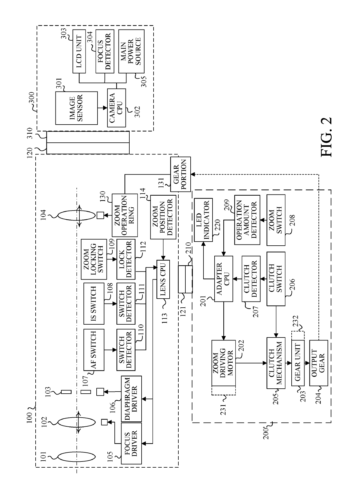
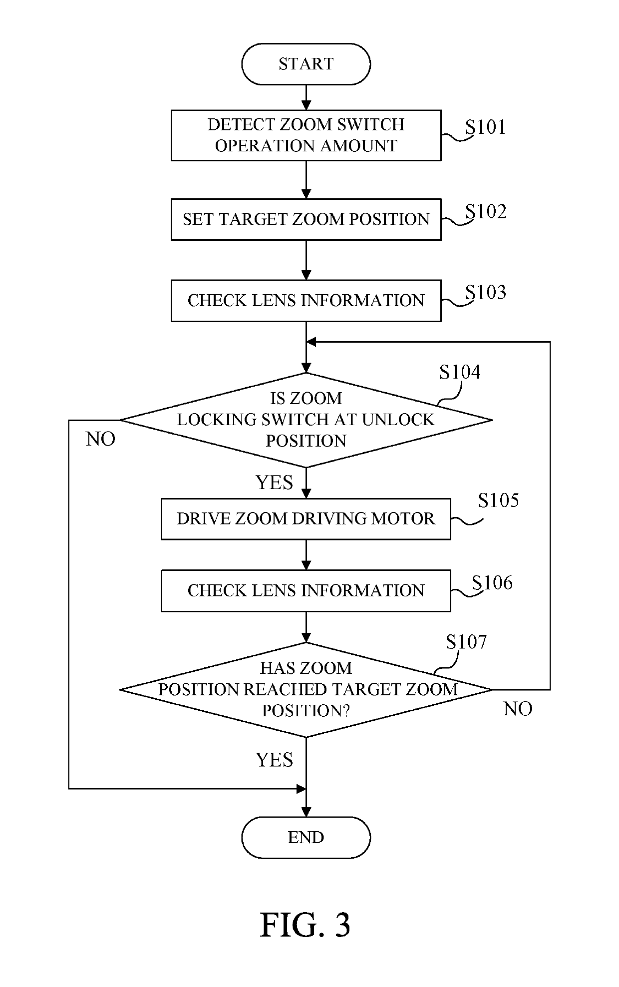
[0041]Next, description will be made of an adapter 200′ that is a second embodiment (Embodiment 2) of the present invention. Embodiment 1 described the case of not driving the zoom driving motor 202 in the adapter 200 when the zoom locking switch 109 is at the locking position. However, only prohibiting the drive of the zoom driving motor 202 may make it hard for the user to understand a reason why the adapter 200 does not start the motor-driven zoom in response to the operation of the zoom switch 208.

[0042]Thus, in this embodiment the adapter 200′ is provided with an LED indicator 220 that lights or blinks to indicate a warning in response to the operation of the zoom switch 208 when the zoom locking switch 109 is at the locking position. It is desirable that the LED indicator 220 have an emission color dedicated for the warning indication, that is, different from a normal emission color for indicating, for example, power-on of the adaptor 200′. Alternately, a similar...

embodiment 3

[Embodiment 3]

[0051]Embodiments 1 and 2 described the case where whether the zoom locking switch 109 is at the locking position or the unlocking position is detected by the lock detector 112 provided in the interchangeable lens 100 and where the adapter CPU 201 communicates with the lens CPU 113 to acquire the lock information indicating the detection result. However, lock detectors (illustrated by dashed lines in FIGS. 2) 231 and 232 provided to the adapter 200 (200′) may detect whether the zoom locking switch 109 is at the locking position or the unlocking position.

[0052]For example, the operation of the zoom switch 208 in the locking state increases a load of the zoom driving motor 202 to increase a current value applied to the motor 202. Thus, the locking state can be detected by detecting that the current value detected by the lock detector 231 as a current detector provided in the zoom driving motor 202 becomes greater than a predetermined value.

[0053]Alternately, a clutch tha...


PUM


Abstract

The optical driver apparatus is detachably attachable to an optical apparatus. The optical apparatus includes a lens operation member operable manually, and a locking mechanism switchable between a locking state of restraining motion of the lens operation member and an unlocking state of releasing the restraint. The optical driver apparatus includes a driver operation member, an actuator configured to move the lens operation member, and a controller configured to control the actuator. The controller is configured to drive the actuator in response to an operation of the driver operation member when the locking mechanism is in the unlocking state and to control the actuator, when the locking mechanism is in the locking state, so as to provide one of a state of not driving the actuator in response to the operation of the driver operation member and a state of performing a warning operation.

Description

BACKGROUND OF THE INVENTION[0001]Field of the Invention[0002]The present invention relates to an optical driver apparatus attachable to optical apparatuses such as video cameras, digital cameras and interchangeable lenses.[0003]Description of the Related Art[0004]Optical apparatuses include ones in which a user's manual operation of an operation member such as a manual operation ring provided around a lens barrel causes a lens to move in its optical axis direction in the lens barrel to perform zooming (variation of magnification) or focusing. However, when the zooming or focusing is performed in video image capturing using such optical apparatuses (interchangeable lenses or cameras), it is often convenient for the user to electrically drive the lens using an actuator.[0005]Japanese Patent Laid-Open No. 2007-108373 discloses an optical driver apparatus that is attached (externally connected) to a lens barrel of an interchangeable lens capable of zooming in response to a user's manual...

Claims


Application Information

Patent Timeline
Patent Type & Authority Patents(United States)
IPC IPC(8): G02B7/09G02B7/04H04N5/232G02B7/28
CPCG02B7/09H04N5/23212G02B7/282G02B7/04G03B5/00G03B17/56G03B2205/0046G03B2205/0053H04N23/672H04N23/673H04N23/634
Inventor NAGAOKA, NOBUYUKI
Owner CANON KK
Why Eureka
Try Eureka