Packer

a packer and packer body technology, applied in the field of downhole packers, can solve the problems of premature packer setting, pbr loading on the packer, and the risk of failure of both the packer element and the pbr

Active Publication Date: 2009-03-31
SPECIALISED GASOLINEEUM SERVICES GROUP
View PDF6 Cites 15 Cited by
  • Summary
  • Abstract
  • Description
  • Claims
  • Application Information

AI Technical Summary

Benefits of technology

[0029]e) anchoring the tool against a wall of t

Problems solved by technology

As many other tools are activated by rotation and indeed as the drill string itself would normally be rotated during this type of operation, it is likely that the packer would prematurely set.
A significant disadvantage of this compression set packer is that of loading on the PBR.
As a result, both the packer element and the PBR are at risk of failure if the load bearing capacity is exceeded.
This is a particular problem in deep wells were the differential pressures will be greater.
As with all weight-set tools there is a risk tha

Method used


Image

  • Packer
  • Packer
  • Packer

Examples


Embodiment Construction

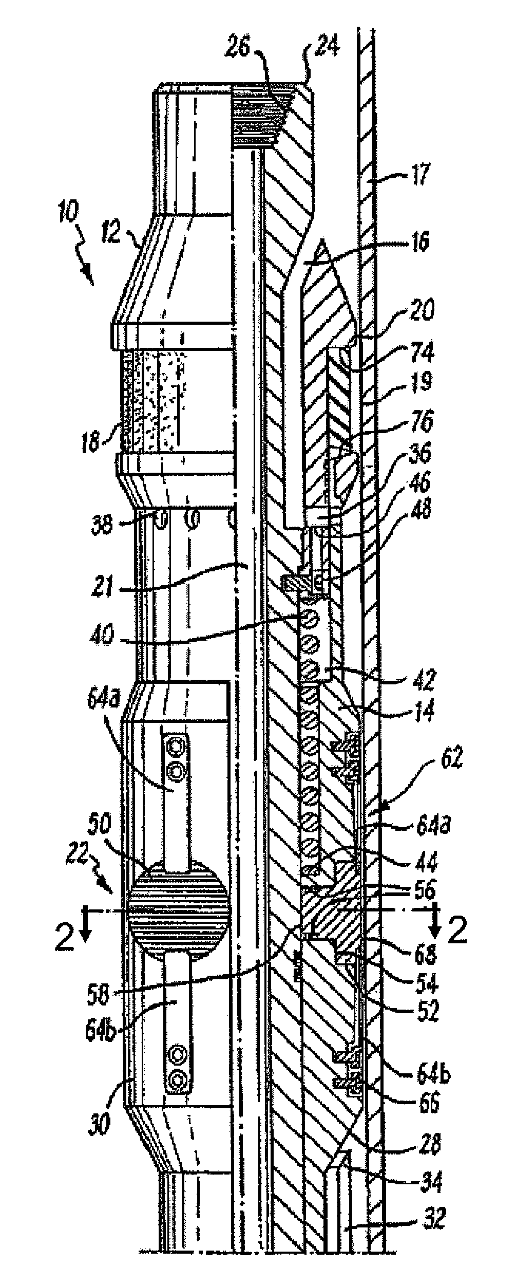
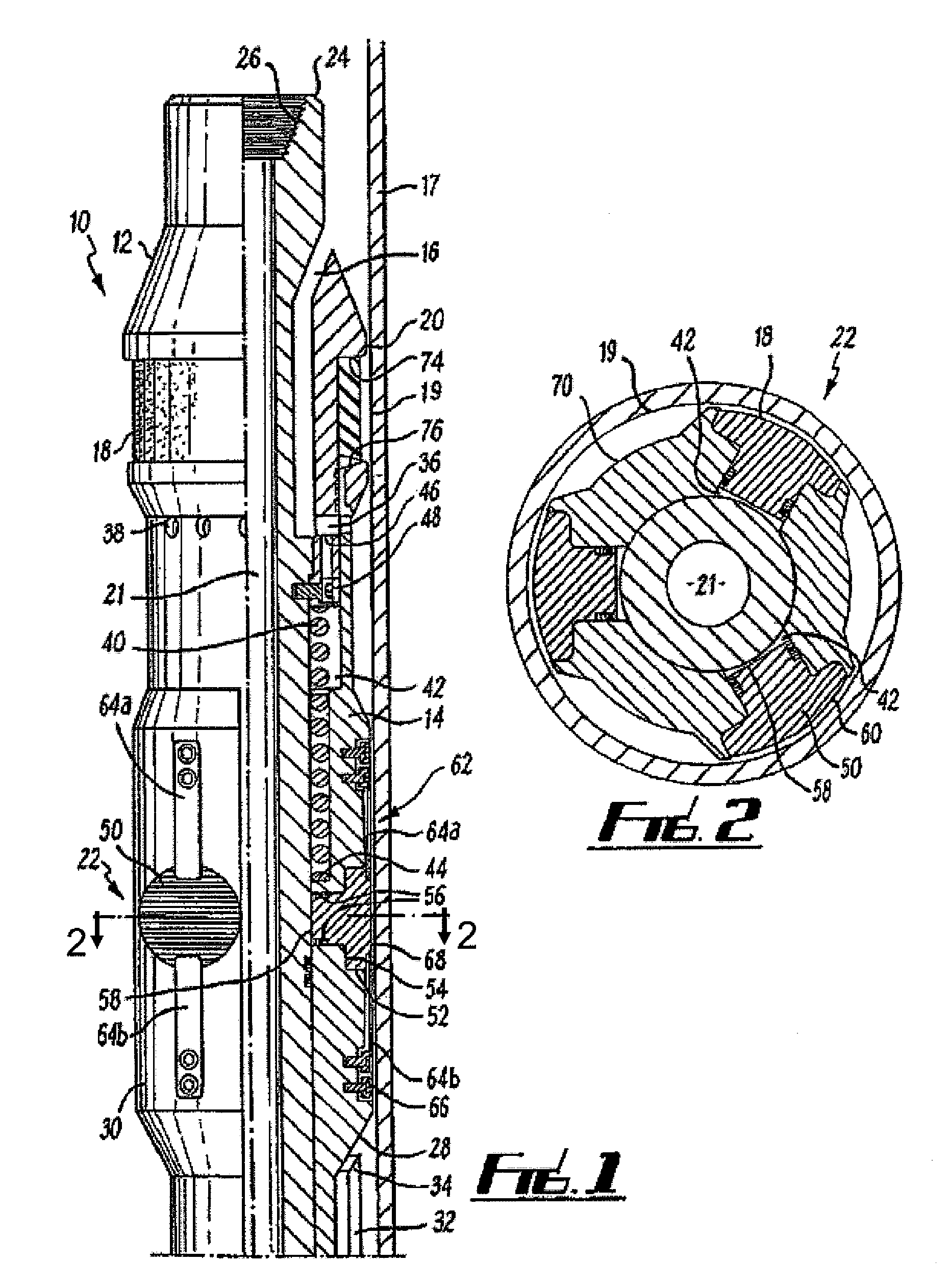
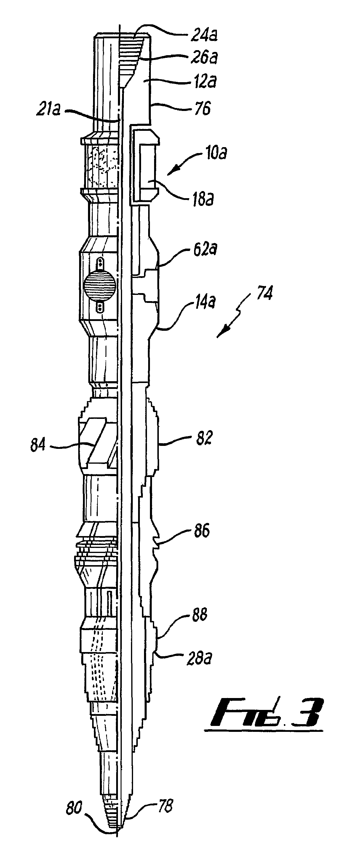
[0044]Reference is initially made to FIG. 1 of the drawings which illustrates a packer tool, generally indicated by reference numeral 10, according to the present invention. Packer tool 10 is a compression set packer.

[0045]The packer tool 10 comprises a body 12 upon which is arranged a packing element 18 and a sleeve 14. Packing element 18 is in the form of an annular band of rubber which when compressed longitudinally will expand radially, increasing the overall diameter of the tool 10 to provide a seal between the outer surface 20 of the body 12 and a surface 19 within a well bore. Packer tool 10 further includes bypass channels 16 behind the packer element 18 and an anchoring means, generally indicated by reference numeral 22, below the packer element 18.

[0046]Tool body 12 is a cylindrical mandrel including a throughbore 21. At an upper end 24, there is located a box section 26 to allow the body 12 to be connected to a work string (not shown). At a lower end of the body 12 there ...


PUM


Abstract

There is disclosed a downhole packer for use in a well bore, and in particular, a packer which can be used for downhole testing. In an embodiment of the invention, a packer tool (10) for mounting on a work string to provide a seal against a tubular (32) is disclosed, the packer tool comprising a body (12) with one or more packer elements (18) and a sleeve (14), the packer tool being set by movement of the sleeve relative to the tool body compressing the one or more packer elements, wherein the tool has a plurality of bypass channels (16) to provide a fluid path past the packer elements, the sleeve including at least owe anchoring member (22, 50), the at least one anchoring member being actuate to contact the tubular by fluid pressure from the bypass channels when the packer is set.

Description

BACKGROUND OF THE INVENTION[0001]The present invention relates to a downhole packer for use in a well bore. More particularly, the present invention relates to a packer which can be used for downhole testing.[0002]During well completions it is desirable to check the integrity of the production bore and any packers used to isolate portions of the well. A known technique for this is to perform an in-flow or negative test. One or more packers are inserted into the well bore to seal off a portion of the well. Low density fluid is introduced to the work string reducing hydrostatic pressure within the pipe. As a consequence of the drop in hydrostatic pressure, well bore fluid flows through any cracks or irregularities into the bore resulting in an increase in pressure which can be monitored and used to indicate where repairs are necessary.[0003]Typically, a separate trip is required to be made into the well to perform an in-flow or negative pressure test. This is because the conventional ...

Claims


Application Information

Patent Timeline
IPC IPC(8): E21B33/1295E21B33/128E21B47/10
CPCE21B33/128E21B47/1025E21B47/117
Inventor TELFER, GEORGE
Owner SPECIALISED GASOLINEEUM SERVICES GROUP
Why Eureka
Try Eureka