Substrate holder and vacuum film deposition apparatus

a vacuum film and substrate technology, applied in the field of substrates, can solve the problems of uneven substrate temperature, increased non-uniformity of vapor-deposited film, so as to prevent excessive load from being applied, uniform heat transmission, accurate adjustment

Inactive Publication Date: 2009-01-01
FUJIFILM CORP
View PDF13 Cites 19 Cited by
  • Summary
  • Abstract
  • Description
  • Claims
  • Application Information

AI Technical Summary

Benefits of technology

[0039]The substrate holder of the present invention can bring the substrate into close contact with the substrate supporting surface with an appropriate load applied to the substrate, thus enabling uniform transmission of heat to the substrate while preventing an excessive load from being applied thereto. The entire surface of the substrate can be thus kept uniform to form a uniform film.
[0040]The vacuum film deposition apparatus of the present invention can bring the substrate into close contact with the substrate supporting surface with an appropriate load applied to the substrate, so the substrate temperature can be accurately adjusted without applying an excessive load, thus enabling a uniform film to be formed on the substrate surface while preventing the substrate from being deformed.

Problems solved by technology

In the substrate holder described in JP 10-147865 A, however, the substrate which is in close contact with the substrate holder when mounted thereon may be gradually separated or displaced from the substrate holder during the film formation on the substrate, causing non-uniformity in the vapor-deposited film formed on the substrate.
Particularly in the case where the substrate temperature is adjusted by heat from the substrate holder, the substrate temperature will become uneven to increase non-uniformity in the vapor-deposited film.
On the other hand, a large load preliminarily applied to the substrate to prevent such displacement of the substrate may cause buckling of the substrate.

Method used


Image

  • Substrate holder and vacuum film deposition apparatus
  • Substrate holder and vacuum film deposition apparatus
  • Substrate holder and vacuum film deposition apparatus

Examples


Embodiment Construction

[0048]On the pages that follow, the substrate holder and the vacuum film deposition apparatus of the present invention are described in detail with reference to the preferred embodiments depicted in the accompanying drawings.

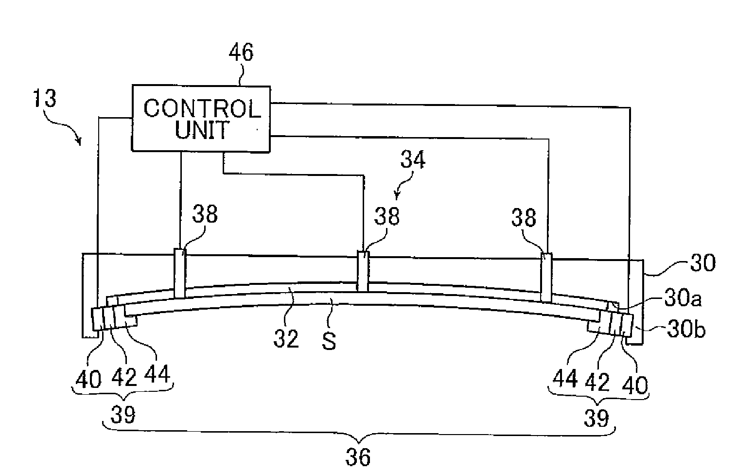
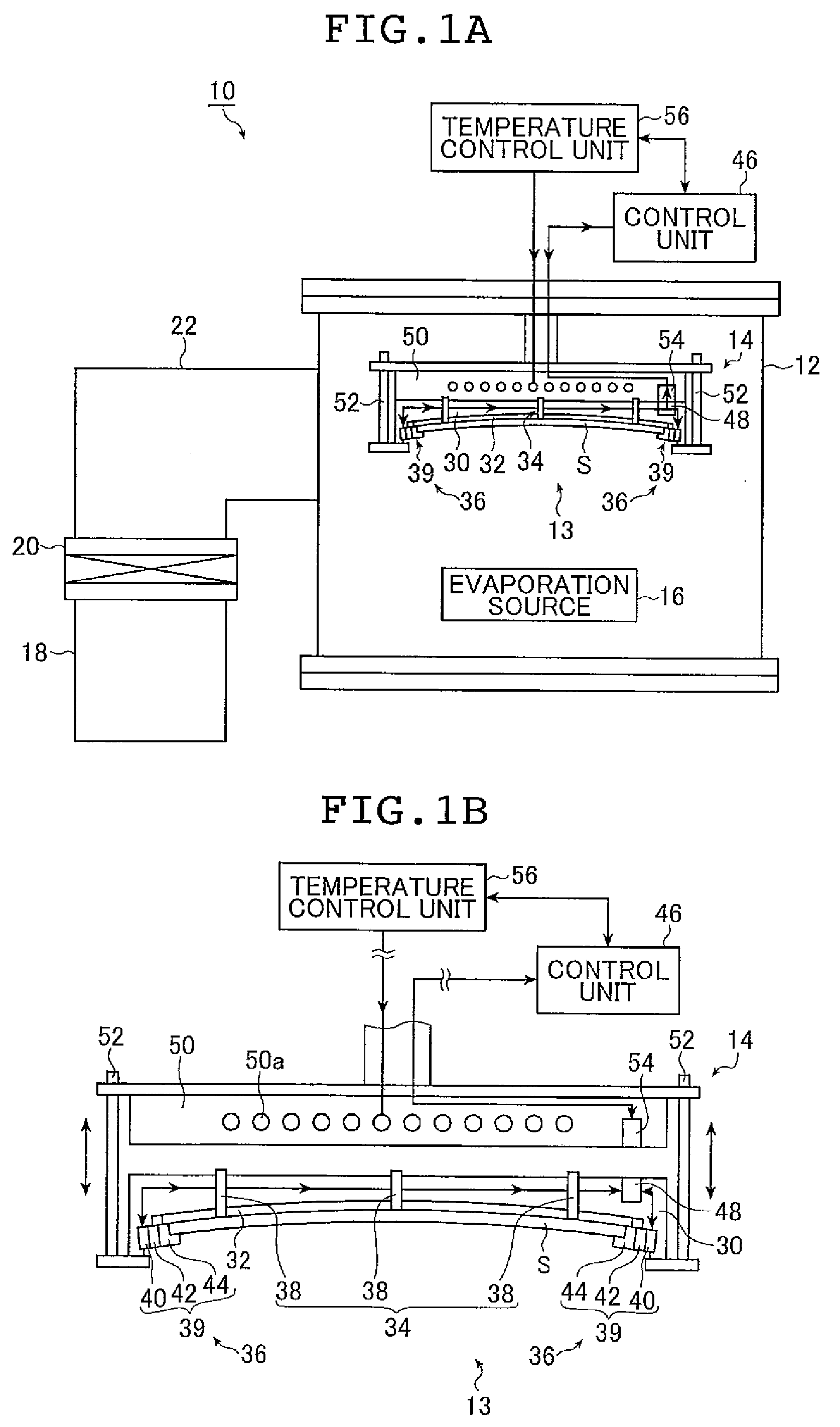
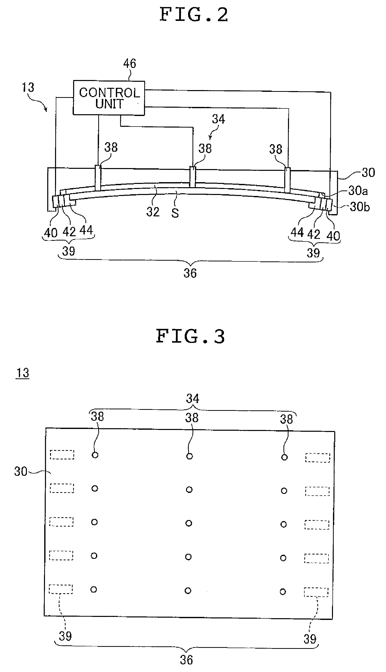
[0049]FIG. 1A is a front view schematically showing the structure of a vacuum evaporation apparatus 10 according to an embodiment of the vacuum film deposition apparatus of the present invention in which the substrate holder of the present invention is used. FIG. 1B is an enlarged front view showing in an enlarged scale a substrate holder 13, a holder mounting section 14 and their peripheries in the vacuum evaporation apparatus 10 shown in FIG. 1A. The substrate holder 13 and the holder mounting section 14 in the vacuum evaporation apparatus 10 are in close contact with each other in FIG. 1A but are not in FIG. 1B.

[0050]The vacuum evaporation apparatus 10 shown in FIG. 1A includes a vacuum chamber 12, the substrate holder 13, the holder mounting section 14, an e...


PUM

PropertyMeasurementUnit
thicknessaaaaaaaaaa
displacementaaaaaaaaaa
temperatureaaaaaaaaaa

Abstract

A vacuum film deposition apparatus in which a film is formed on a substrate by a vacuum film deposition process includes a holder which has a substrate supporting surface which is in a curved shape and is brought into contact with the substrate. A substrate holder for holding the substrate includes a base having the substrate supporting surface. The apparatus and the substrate holder further include a contact detection mechanism which detects a state of contact between the substrate and the substrate supporting surface, a load applying mechanism which is provided outside the substrate supporting surface and supports the substrate by applying a load to end faces of the substrate and a control unit which controls the load the load applying mechanism applies to the substrate based on output from the contact detection mechanism.

Description

[0001]The entire contents of a document cited in this specification are incorporated herein by reference.BACKGROUND OF THE INVENTION[0002]The present invention relates to a substrate holder for holding a substrate and a vacuum film deposition apparatus used in forming a film on the substrate held on the substrate holder by a vacuum film deposition method.[0003]A radiation image detector which records a radiation image by first allowing a radiation (e.g. X-rays, α-rays, β-rays, γ-rays, electron beams or uv rays) to pass through an object, then picking up the radiation as an electric signal has conventionally been used in such applications as medical diagnostic imaging and industrial nondestructive testing.[0004]Examples of this radiation image detector include a solid-state radiation detector (so-called “flat panel detector” which is hereinafter abbreviated as “FPD”) that picks up the radiation as an electric image signal, and an X-ray image intensifier that picks up the radiation im...

Claims


Application Information

Patent Timeline
Patent Type & Authority Applications(United States)
IPC IPC(8): C23C16/00
CPCC23C14/50H01L21/68728H01L21/67288H01L21/67092
Inventor SOHDA, HIROSHI
Owner FUJIFILM CORP
Why Eureka
Try Eureka