Phase change heat storage element and heat storage and supply device adopting same

A phase-change heat storage and heat supply device technology, which is applied in the direction of household heat supply, heat storage equipment, and heat supply systems, can solve the problems of poor adaptability of heat sources, many heat exchange links, and long heat release time to achieve adaptability strong effect

Inactive Publication Date: 2012-07-04
HUNAN HUITONG HEAT SOURCE TECH
View PDF9 Cites 15 Cited by
  • Summary
  • Abstract
  • Description
  • Claims
  • Application Information

AI Technical Summary

Problems solved by technology

[0002] At present, the phase change heat storage technology is widely used, especially the mobile heat storage heat supply device as a supplementary facility for heating network heating and self-contained boiler heat supply is developing rapidly. The current phase change heat storage heat supply devices mainly include heat storage bodies There are several forms of heat storage, such as integral heat storage, tubular heat storage element unit heat storage, heat storage ball unit heat storage, etc., but the following problems generally exist: 1) The adaptability to heat sources is poor. Design the waste heat boiler properly, and then provide steam or hot water to the mobile heat storage and heating device, which increases the investment in equipment; 2) Heat storage and heat supply need to transfer heat through a heat transfer medium, there are many heat exchange links, and the heat The attenuation is large, and the heat charging and heat release time is long; 3) Part of the heat storage body is an integral heat storage and heat supply device. Steam or water completes heat storage and heat extraction through coils buried in the heat storage body, and steam The temperature of the condensed water discharged during the heat storage of the heat storage coil is as high as 80°C, resulting in a low utilization rate of heat resources; when the cold water passes through the coil buried in the heat storage body to obtain heat, the air blockage phenomenon is serious and cannot be carried out smoothly. take heat

Method used


Image

  • Phase change heat storage element and heat storage and supply device adopting same
  • Phase change heat storage element and heat storage and supply device adopting same
  • Phase change heat storage element and heat storage and supply device adopting same

Examples


Embodiment 1

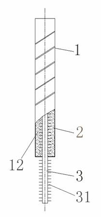
[0025] The structure of the phase change heat storage element of this embodiment is as attached figure 1 As shown, a housing 1 is included, and a hollow cavity 12 is provided inside the housing 1. The hollow cavity 12 is also provided with a heat pipe 3. The side of the heat pipe 3 is provided with fins 31, and one end of the heat pipe 3 is placed in the hollow cavity. Inside the body 12, the other end is exposed outside the shell 1, the hollow cavity 12 is filled with a phase change heat storage material 2, and the end of the heat pipe 3 placed in the hollow cavity 12 is surrounded by the phase change heat storage material 2 . In this embodiment, the casing 1 is a special-shaped tubular metal shell, and the number of heat pipes 3 can be one or more.

[0026] When the phase-change heat storage element of this embodiment is used, when heat is stored, the heat of the heat source is directly transferred to the phase-change heat storage material 2 in the hollow cavity 12 through ...

Embodiment 2

[0028] The structure of the phase change heat storage element of this embodiment is similar to that of Embodiment 1, the difference is that: the middle part of the heat pipe 3 is placed in the hollow cavity 12, and the two ends of the heat pipe 3 are exposed outside the casing 1, and the number of the heat pipe 3 can also be One or more.

[0029] When the phase change heat storage element of this embodiment is used, the heat from the heat source can be directly transferred to the phase change heat storage material 2 in the hollow cavity 12 through both ends of the heat pipe 3 .

Embodiment 3

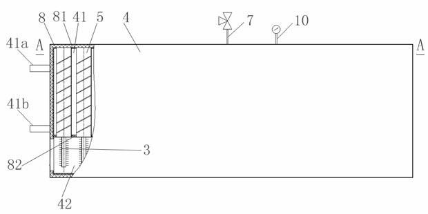
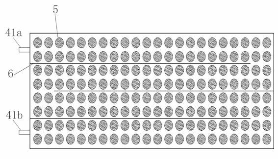
[0031] The heat storage heat supply device structure of this embodiment is as attached figure 2 , 3 As shown, the box body 4 is included, and the inner surface of the box body 4 is provided with an insulating layer 8. The outer shape of the box body 4 in this embodiment is a cuboid, and of course it can also be a cylinder or other polygonal prisms. The inside of the box body 4 is divided into a phase change heat storage chamber 41 and a heat supply heating chamber 42 by a partition plate 82. The phase change heat storage chamber 41 is provided with a cold water inlet 41a and a hot water outlet 41b, and the phase change heat storage chamber 41 is evenly distributed A plurality of phase-change thermal storage elements 5 described in Embodiment 1 are installed, the lower end of the housing 1 of the phase-change thermal storage element 5 is fixed on the partition plate 82, and the upper end of the housing 1 is fixed on the top of the phase-change thermal storage chamber 41. On t...


PUM


Abstract

The invention discloses a phase change heat storage element and a heat storage and supply device adopting the same. The phase change heat storage element comprises a shell, wherein a hollow cavity is formed in the shell; a phase change heat storage material is filled in the hollow cavity; a heat pipe is arranged in the hollow cavity; and part of the heat pipe is exposed out of the shell. The heat pipe is used for transmitting heat, so that the heat storage time of the phase change heat storage element disclosed by the invention is short. The heat storage and supply device comprises a box body, wherein a phase change heat storage chamber and a heat supply heating chamber are formed in the box body; a cold water inlet and a hot water outlet are formed in the phase changer heat storage chamber; a heat source inlet is formed in the heat supply heating chamber; at least one phase change heat storage element is arranged in the phase change heat storage chamber; and the part, exposed out of the shell, of the heat pipe arranged in the phase change heat storage element is arranged in the heat supply heating chamber. The phase change heat storage chamber and the heat supply heating chamber are separated from each other, so that the heat pipe can be heated by using industrial smoke or media, such as steam, hot water and the like; and therefore, the phase change heat storage element can well adapt to outside heat sources.

Description

technical field [0001] The invention belongs to energy storage and release technology, in particular to a phase change heat storage element and a heat storage heat supply device using the element. Background technique [0002] At present, the phase change heat storage technology is widely used, especially the mobile heat storage heat supply device as a supplementary facility for heating network heating and self-contained boiler heat supply is developing rapidly. The current phase change heat storage heat supply devices mainly include heat storage bodies There are several forms of heat storage, such as integral heat storage, tubular heat storage element unit heat storage, heat storage ball unit heat storage, etc., but the following problems generally exist: 1) The adaptability to heat sources is poor. Design the waste heat boiler properly, and then provide steam or hot water to the mobile heat storage and heating device, which increases the investment in equipment; 2) Heat st...

Claims


Application Information

Patent Timeline
Patent Type & Authority Applications(China)
IPC IPC(8): F28D20/02F24D11/00
CPCY02E60/145Y02E60/14
Inventor 曾东和朱志坚戴利军资静斌
Owner HUNAN HUITONG HEAT SOURCE TECH
Why Eureka
Try Eureka