Power brace spanner

a power bracing and spanner technology, applied in the field of reinforcement and/or bracing of foundations, can solve the problems of reducing the interior space of the foundation, reducing the service life of the foundation, so as to achieve the effect of maximizing the interior spa

Active Publication Date: 2019-08-27
POWER BRACE
View PDF49 Cites 2 Cited by
  • Summary
  • Abstract
  • Description
  • Claims
  • Application Information

AI Technical Summary

Benefits of technology

[0005]Therefore, it is a primary object, feature, and / or advantage of the invention to improve on and / or overcome the deficiencies in the art.
[0006]It is another object, feature, and / or advantage of the invention to provide a joist spanner assembly with slidably connected inner and outer brackets configured to be positioned between two adjacent joist members. Wherein the brackets may include top, bottom, side, and rear surfaces.
[0007]It is yet another object, feature, and / or advantage of the invention to provide a joist spanner assembly wherein the rear surface of the inner and outer brackets each comprise an elongated aperture or slot configured to slidably align.
[0008]It is a further object, feature, and / or advantage of the invention to provide a joist spanner assembly wherein the side surfaces of the inner bracket and outer bracket are configured to abut adjacent members.
[0009]It is still a further object, feature, and / or advantage of the invention to provide a wall support system including a joist spanner assembly and a generally vertical support member with first and second ends. Wherein the joist spanner is positioned between two adjacent joist members and the first end of the vertical support member may be slidably attached to the spanner assembly by a fastener passing through an inner slot and an outer slot of the inner bracket and outer bracket respectively. The second end of the vertical support member may be secured proximate to the floor.
[0010]It is still yet a further object, feature, and / or advantage of the invention to provide a wall reinforcement system that maximizes the interior space proximate to the wall and is aesthetically pleasing.

Problems solved by technology

As a result, upon exposure to excessive lateral forces, foundation walls often crack, bow, push inward, or even collapse.
The foundation reinforcement systems commonly known in the art are deficient for a variety reasons.
For example, wall anchoring systems counteract soil pressure by anchoring walls to stable, undisturbed soil outside the wall, which often requires significant excavation of surrounding earth.
Further, given the varying types of soils outside of the wall, such systems are prone to failure.
Many indoor foundation reinforcement systems occupy a large amount of interior space.
For example, braces extending diagonally from the floor to the foundation wall significantly limit interior space of a room proximate to the foundation wall, often limiting overall function and enjoyment of the room.
However, tying a support system directly into the ceiling and / or floor joists may limit the spacing of the support members to match the existing joist spacing.

Method used


Image

  • Power brace spanner
  • Power brace spanner
  • Power brace spanner

Examples


Embodiment Construction

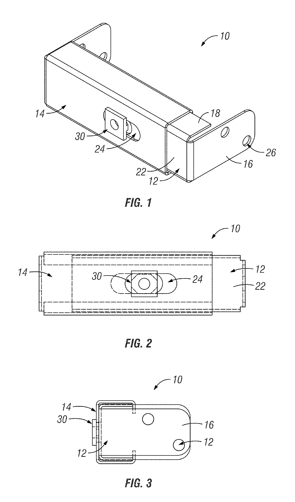
[0040]The invention is directed towards a system, method, and apparatus that includes a spanner assembly 10. The spanner assembly 10 may be utilized as a component of a wall reinforcement system 38. An example of a wall reinforcement system 38 is shown and described in U.S. Ser. No. 14 / 932,225, now U.S. Pat. No. 9,422,734, which is herein incorporated by reference in its entirety.

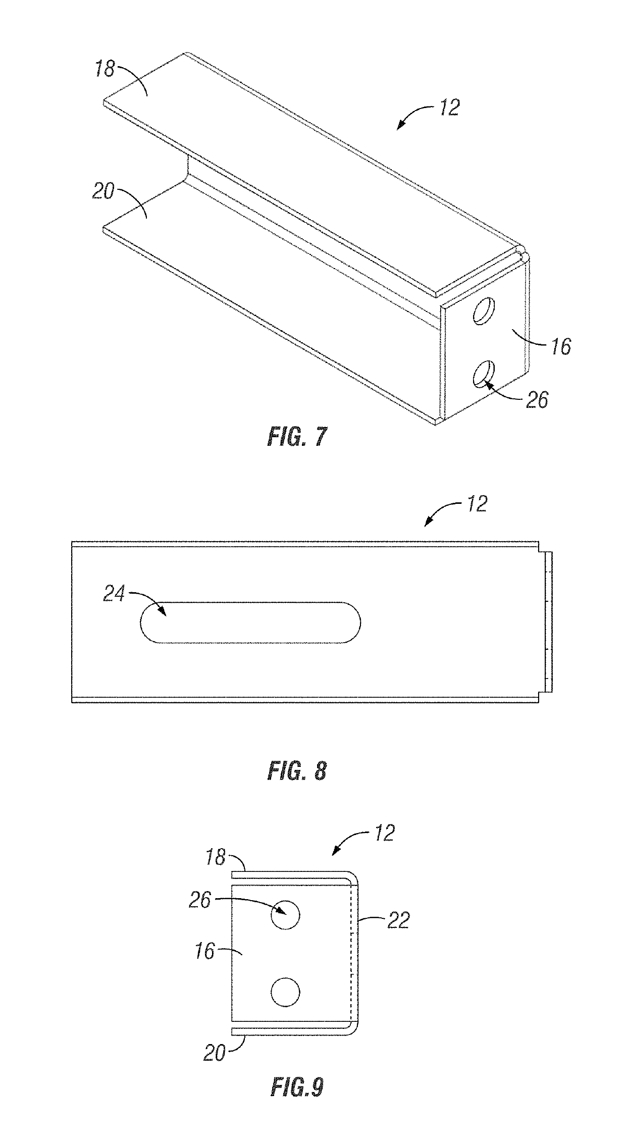
[0041]Referring to FIGS. 1-3, various views of an example embodiment of a spanner assembly 10 is shown. A spanner assembly 10 may include an inner bracket 12 and an outer bracket 14 in slidable or telescopic communication with one another. An example embodiment of the brackets 12 and 14 is shown in FIGS. 7-9. The inner 12 and outer brackets 14 may each include a side surface 16, top surface 18, a bottom surface 20, and a rear surface. The outer bracket 14 may be sized to allow for the inner bracket 12 to be slidably inserted within a cavity or aperture defined by the various surfaces of the outer bracket 14...


PUM


Abstract

An improved system for straightening and / or supporting a wall is provided. The system includes a joist spanner system that may be attached to an elongated vertical member positioned to abut a wall. The joist spanner system may include an inner bracket and an outer bracket in slidable or telescopic communication with one another. The inner bracket and outer bracket may each include a slot or track to provide slidable or telescopic adjustment of the spanner system. The slot or track may also provide an adjustable point for attaching the spanner system to the elongated vertical member. The inner bracket and outer bracket may also each include an end plate configured to be positioned to abut opposing joist members. The end plates may also include one or more apertures configured to receive a fastener for securing the spanner system to opposing joist members.

Description

FIELD OF THE INVENTION[0001]The present disclosure relates generally to reinforcing and / or bracing of a foundation. More particularly, but not exclusively, the present disclosure relates to a system and method for straightening and / or supporting a wall, particularly a wall that has been damaged due to expansive soils, hydrostatic pressure, freezing ground water, and / or other reasons. Even more particularly, but not exclusively, the present disclosure relates to a system and method for straightening and / or supporting a wall that includes a spanner configured to allow a vertical support member to be positioned at a location between two joists.BACKGROUND OF THE INVENTION[0002]Many of today's homes include basements, which are at least partially subterranean. The basement foundation walls are designed to support vertical loads more so than lateral loads from the surrounding earth. As a result, upon exposure to excessive lateral forces, foundation walls often crack, bow, push inward, or ...

Claims


Application Information

Patent Timeline
Patent Type & Authority Patents(United States)
IPC IPC(8): E04G23/02E02D37/00E02D31/14E02D31/12
Inventor HEADY, TIMOTHY P.HEADY, CHARLES W.
Owner POWER BRACE
Why Eureka
Try Eureka