Intelligent polisher/buffer with selective color-matching light

a polisher and selective technology, applied in the direction of semiconductor devices for light sources, lighting and heating apparatus, light source combinations, etc., can solve the problems of inability to inability to accurately achieve an acceptable car, and compromised vehicle surfaces

Active Publication Date: 2019-09-03
R B L PROD L
View PDF7 Cites 4 Cited by
  • Summary
  • Abstract
  • Description
  • Claims
  • Application Information

AI Technical Summary

Problems solved by technology

Often vehicle surfaces are compromised during the painting process, and cars with visible scratches are not acceptable.
There is no exact science to achieving an acceptable result other than providing a skilled operator with an air polisher and a pad.
However, these machines can remove paint from a vehicle very quickly, requiring careful use of the variable speed control.
Regardless of the system used, new paint system chemistry is making vehicle surface polishing much more difficult.
In particular, new paint is harder and it takes longer to remove the defects.
If more aggressing procedures are used the process can “go too far” and remove too much of the painted surface.
If a light source casts a wavelength other than “pure white” onto a painted surface, the true color and condition of paint defects cannot be accurately perceived.
K or below are undesirable for surface polishing, since warm tones of light are cast onto the surface.
Thus, while incandescent lighting, in the range of 2700K-3300K, provides warm tones for household environments it is a poor choice for surface detailers.
Halogen light at ˜2700K is one of the worst sources for bringing out painted surface defects, and while compact fluorescent lighting CFL at ˜2700-4200K is better but it can still generate undesirable color tinting.
While there are power-driven polishers with means for illuminating the work surface, such devices are not intended for painted surfaces, nor do they provide an appropriate light source.
Clearly such apparatus would not be suitable for polishing or buffing modern painted vehicle surfaces.

Method used


Image

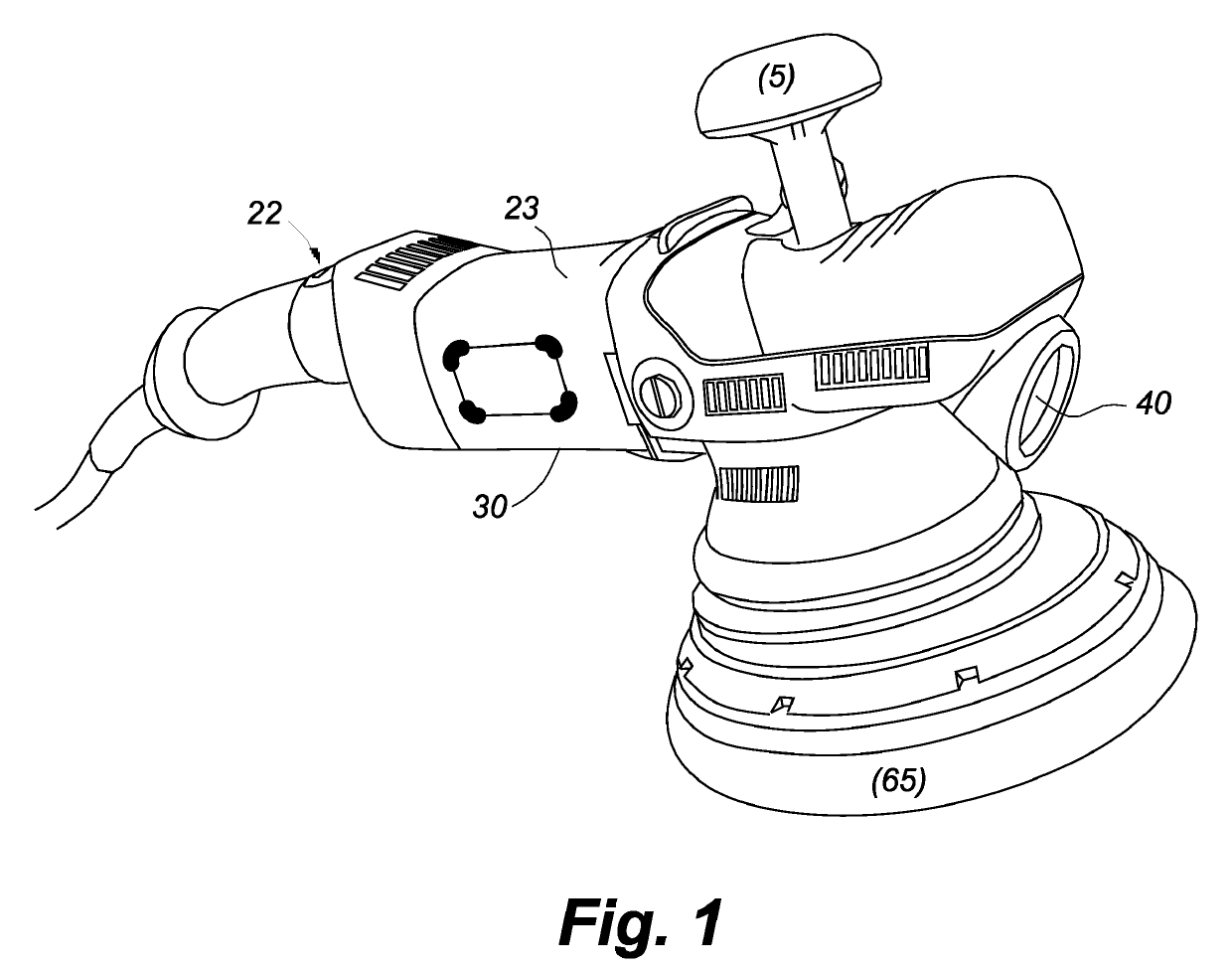
  • Intelligent polisher/buffer with selective color-matching light
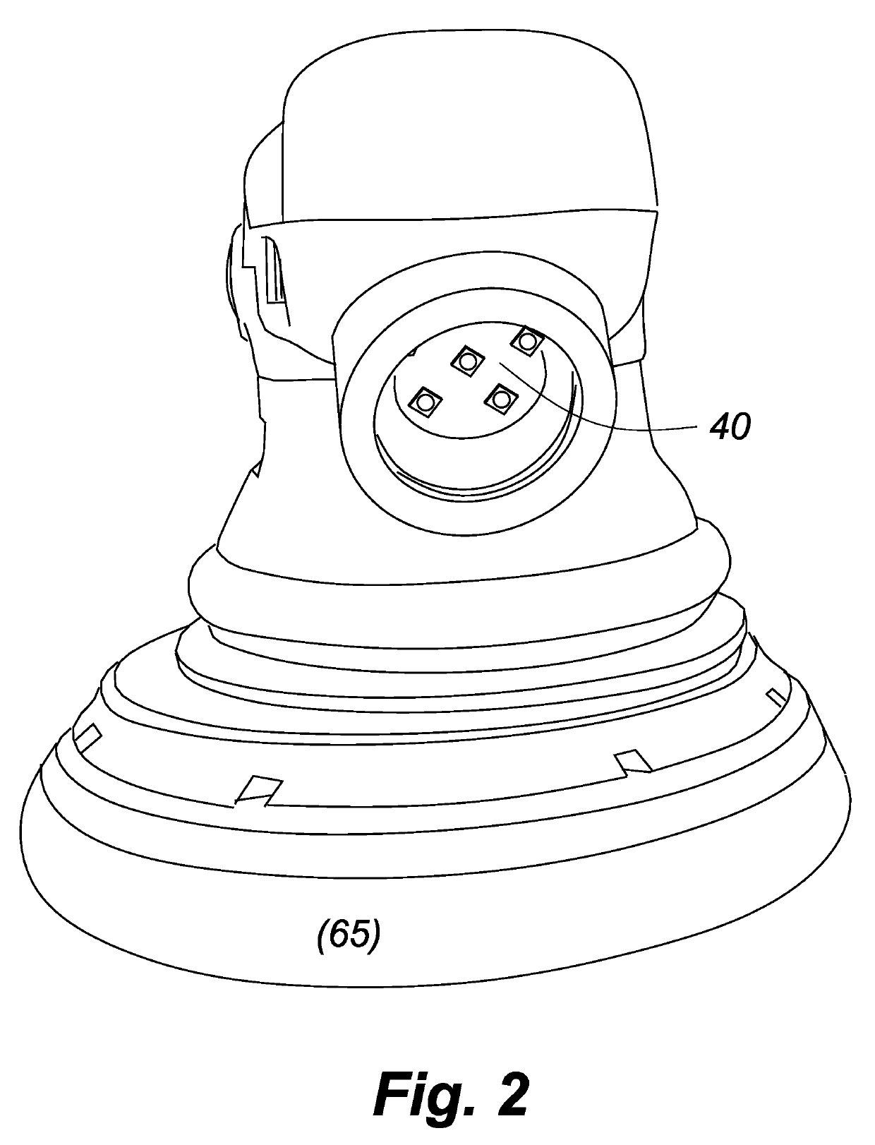
  • Intelligent polisher/buffer with selective color-matching light
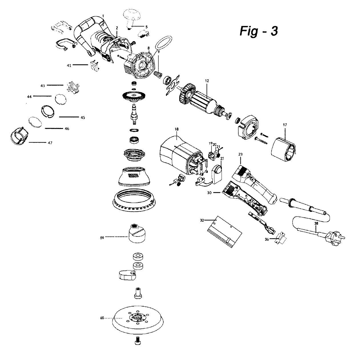
  • Intelligent polisher/buffer with selective color-matching light

Examples


Embodiment Construction

[0015]Prior to describing the invention in detail, certain definitions will be provided as follows:[0016]1) A Lumen of light refers to a measure the relative intensity or brightness from a single source, such as the amount of light generated by one candle.[0017]2) The Kelvin Scale is an extension of the Celsius scale based on the color of the light emitted from a hypothetical “black body.” The Kelvin scale refers to the amount of energy needed to transform a black body into a corresponding color expressed with a numerical value in (degrees) K.[0018]3) Color Temperature refers to the perceived color of a light source, as interpreted by the human eye, measured in the Kelvin scale. Colors with lower Kelvin temperatures are considered “warm,” as they containing orange to red light, whereas colors with higher Kelvin temperatures are considered “cool” (i.e., more blue light).[0019]4) Daylight is taken to mean “normal daylight” at mid-day, when the sun is at its highest point in the sky, w...


PUM

PropertyMeasurementUnit
diameteraaaaaaaaaa
color temperatureaaaaaaaaaa

Abstract

An improved buffer / polisher for treated painted surfaces, including painted cars, automobiles, vehicles and the like, including surfaces with state-of-the-art, hardened coats of paint or finish, includes built-in source of illumination, disposed on the housing, direct light downwardly and toward the work surface. The source of illumination emits light with a color temperature above 4500 degrees Kelvin, more preferably at 5000 degrees Kelvin or greater. Even more preferably, the source of illumination is switchable to include light with a color temperature including 5000 degrees Kelvin (mimicking daylight at 10-11 am) and 6500K (mimicking daylight at 12 noon). The source of illumination may comprise one or more LEDs, and the polishing pad may assume a random orbital motion.

Description

FIELD OF THE INVENTION[0001]This invention relates to painted surface polishing and buffing and, more particularly, to an intelligent polisher with multiple surface illumination settings.BACKGROUND OF THE INVENTION[0002]Polishing small defects in the painted surfaces of automotive and other vehicles is a critical operation. Often vehicle surfaces are compromised during the painting process, and cars with visible scratches are not acceptable. There is no exact science to achieving an acceptable result other than providing a skilled operator with an air polisher and a pad. Polish is applied to the pad, the trigger is depressed, and after a few seconds the scratches usually go away.[0003]There are basically two different types of paint polishers or buffers: rotary and orbital. Rotary units are still the most popular, as they are very effective at removing deep scratches, and overall paint polishing. However, these machines can remove paint from a vehicle very quickly, requiring careful...

Claims


Application Information

Patent Timeline
Patent Type & Authority Patents(United States)
IPC IPC(8): B24B1/00B24B23/02B24B23/04F21V23/04F21V33/00B24D7/14B24D7/18F21Y113/13F21Y115/10
CPCB24B23/028B24B1/00B24B23/04F21V33/0084F21Y2113/13F21Y2115/10B24D7/14B24D7/18F21V23/0414
Inventor LIPSON, RONALD
Owner R B L PROD L
Why Eureka
Try Eureka