Portable folding wagon

a folding wagon and folding frame technology, applied in the field of portable folding wagons, can solve the problems of shortening the service life of the folding frame and requiring improvement in the security of the produ

Active Publication Date: 2019-09-03
XIAMEN ROADZUP OUTDOOR PROD
View PDF8 Cites 16 Cited by
  • Summary
  • Abstract
  • Description
  • Claims
  • Application Information

AI Technical Summary

Benefits of technology

[0017]The bottom connecting base is disposed with a through hole, the support rod passes through the through hole, the support rod is further rotatably connected to the bottom connecting base, the bottom connecting base is rotatably connected to a support rod, the bottom end of the support rod passes through the surrounding wall and the through hole and connects to the wheel, the top end of ht support rod is rotatably connected to a sliding connecting piece, the sliding connecting piece is slidably connected to the scissor unit of the scissor mechanism. It brings following effects: firstly, the top end of the support rod is connected to the scissor unit by the sliding connecting piece, the moving connecting of the support rod and the scissor unit can absorb or partially absorb the torque of the support rod during the folding, unfolding or walking; secondly, the top end of the support rod is connected to the scissor unit by the sliding connecting piece, so the folding and unfolding are convenient and labor saving; thirdly, with the support rods, the material and the material cost are reduced; fourthly, the hand would not be stuck during the folding and unfolding, the usage security is enhanced; fifthly, the structure is compact and convenient to assemble, the connecting strength of the support rod and the bottom connecting base is enhanced.
[0018]The folding frame further comprises a bottom frame, the bottom frame comprises radial mechanisms arranged front and back with the same number as the scissor units of the first scissor mechanism, the radial mechanism comprises a central base and four bottom rods rotatably connected to the central base, the end of the bottom rod of the radial mechanism is rotatably connected to the first central connecting base or the bottom connecting base correspondingly, each first central connecting base is connected to the radial mechanism, avoiding the central portion of the first scissor mechanism shaking or swing and improving the solidity of the support of the bottom portion.
[0019]The first central connecting base is connected to the end of one bottom rod of two adjacent radial mechanisms at the same time, the structure is simplified and the solidity is improved.
[0020]The first central connecting base comprises fixedly connected two second bottom rotating joints and two central rotating joints, the structure is simplified and the solidity is improved.
[0022]The pull rod mechanism comprises two first pull rods, a second pull rod and an assembly base, the two first pull rods are arranged with space; one end of the two first pull rods are rotatably connected to the position base, while the other end of the two first pull rods are fixedly connected by the assembly base; the second pull rod is rotatably connected to the assembly base, the second position groove is disposed at the assembly base. The connecting is solid and stable.

Problems solved by technology

Existing portable folding wagons have disadvantages: firstly, the flexible pipes of the folding frame always keep in vertical state that they are subjected to torque during the folding, unfolding and being pulled, resulting in a shortened service life of the folding frame; secondly, the flexible pipe comprises two pipes that they use much material and cost much; thirdly, the flexible pipe might stack one's hand during the unfolding, so the usage security of the products need improvement.

Method used


Image

  • Portable folding wagon
  • Portable folding wagon
  • Portable folding wagon

Examples


Embodiment Construction

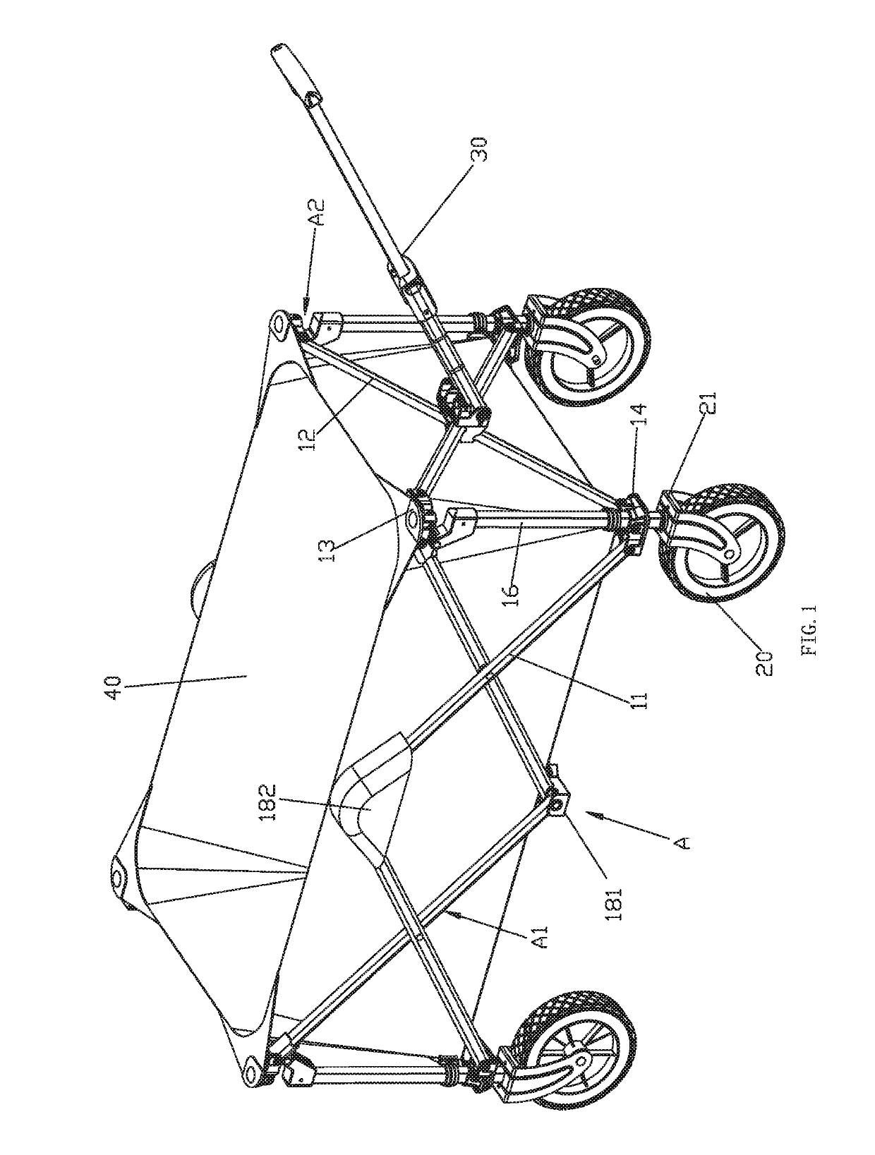
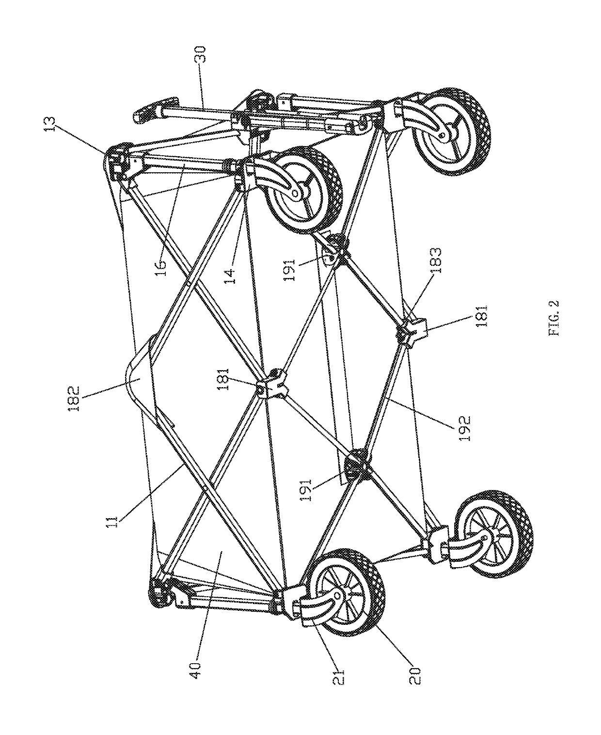
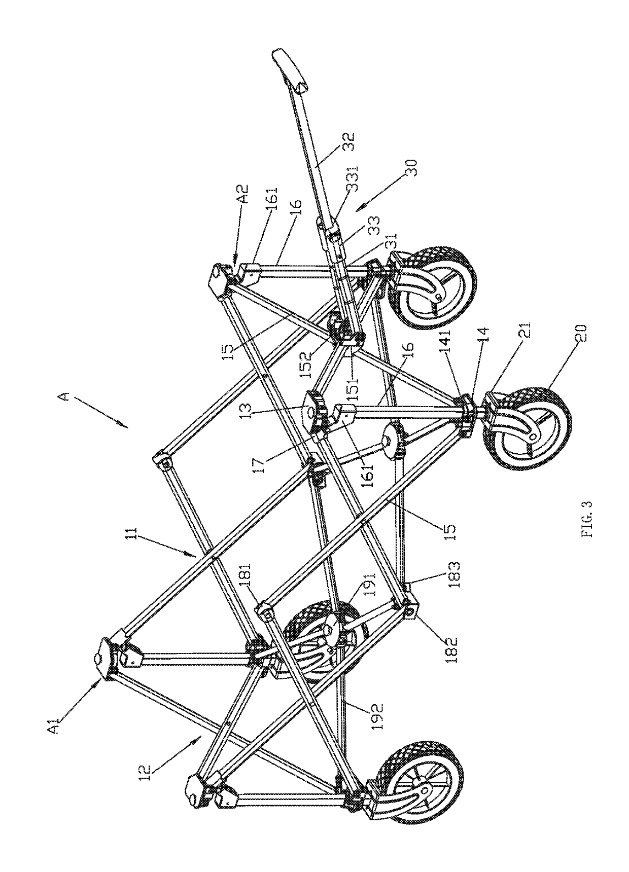
[0034]The portable folding wagon, as figured in FIGS. 1-10, comprises a wagon frame A, the wagon frame A comprises a folding frame A1, wheels 20 and a pull rod mechanism 30.

[0035]The folding frame A1 comprises four scissor mechanisms surrounding in a rectangle and a bottom frame. The folding frame A1 is foldable to be in a folding state or unfolding state.

[0036]The four scissor mechanism comprises two first scissor mechanisms 11 arranged left and right and two second scissor mechanisms 12 arranged front and back. The first scissor mechanism 11 comprises two scissor units arranged front and back; the second scissor mechanism 12 comprises a scissor unit; but the numbers of the scissor units of the first and second scissor mechanisms are not limited. The top portions of each two adjacent scissor mechanisms are rotatably connected by a top connecting base and the bottom portions are rotatably connected by a bottom connecting base, forming a sleeve frame with a rectangle top view. The sc...


PUM


Abstract

A portable folding wagon includes a wagon frame with a folding frame and wheels. The folding frame has four scissor mechanisms, each mechanism has at least a scissor unit. The top portions of two adjacent scissor mechanisms are rotatably connected by a top connecting base, the bottom portions are rotatably connected by a bottom connecting base; the bottom connecting base is rotatably connected to a support rod, the bottom connecting base is disposed with a through hole, the top periphery of the through hole of the bottom connecting base extends upwardly to form a surrounding wall for the support rod to pass through, the bottom end of the support rod passes through the surrounding wall and the through hole and connects to the wheel, the top end of the support rod is rotatably connected to a sliding connecting piece, the sliding connecting piece is slidably connected to the scissor unit.

Description

TECHNICAL FIELD[0001]The present invention relates to a portable folding wagon.RELATED ART[0002]Existing portable folding wagons, for example disclosed in the publishing numbers of CN201210293571.X, CN201210572499.4 and U.S. Pat. No. 9,073,564B2, comprises a wagon frame, which comprises a folding frame and wheels. The folding frame comprises four scissor mechanisms surrounding in a rectangle and four flexible pipes. The scissor mechanism comprises at least one scissor unit, the top portions of each two adjacent scissor mechanism are rotatably connected by a top connecting base, the bottom portions are rotatably connected by a bottom connecting base; the top end of the flexible pipe is fixedly connected to the top connecting base, the bottom end fixedly passes through the bottom connecting base. The wheels are assembled to the bottom end of the flexible pipes. Existing portable folding wagons have disadvantages: firstly, the flexible pipes of the folding frame always keep in vertical...

Claims


Application Information

Patent Timeline
Patent Type & Authority Patents(United States)
IPC IPC(8): B62B3/02B62B3/00B62B5/06
CPCB62B3/001B62B3/002B62B3/025B62B5/06B62B2205/02B62B2205/06B62B2301/044B62B3/02B62B5/00B62B3/003B62B3/007B62B5/067
Inventor HUANG, CHANGJIU
Owner XIAMEN ROADZUP OUTDOOR PROD
Why Eureka
Try Eureka