Drainage apparatus

a technology of draining apparatus and draining pipe, which is applied in the direction of draining pipes, mechanical equipment, other washing machines, etc., can solve the problems of leaking through, difficulty in keeping and maintaining drainage paths, and inability to achieve smooth and efficient drainag

Active Publication Date: 2019-09-03
LG ELECTRONICS INC
View PDF25 Cites 0 Cited by
  • Summary
  • Abstract
  • Description
  • Claims
  • Application Information

AI Technical Summary

Benefits of technology

[0007]Accordingly, the present invention is provided to address the above-noted and other problems. An object of the present disclosure is to provide a drainage apparatus which is capable of preventing the fluid flowing from two paths from meeting and splashing to leak to a third inlet hole.
[0021]The drainage apparatus in accordance with the embodiments of the present disclosure has an effect of preventing the fluid meeting after flowing from two paths from leaking to the third inlet hole.

Problems solved by technology

The laundry treatment apparatus exemplified above is likely to have the wash water contaminated during the washing process and the water condensed during the drying process generated in two apparatuses, respectively.
However, the laundry treatment apparatus has two or more drainage paths when draining the contaminated wash water and the condensed water generated in the apparatuses outside and it is then to difficult to keep and maintain the drainage paths.
If the wash water splashes, drainage flux fails to become smooth and efficient and it might leak through a third flow path.

Method used


Image

  • Drainage apparatus
  • Drainage apparatus
  • Drainage apparatus

Examples


Embodiment Construction

[0030]Description will now be given in detail according to exemplary embodiments disclosed herein, with reference to the accompanying drawings. The accompanying drawings are used to help easily understand various technical features and it should be understood that the embodiments presented herein are not limited by the accompanying drawings. As such, the present disclosure should be construed to extend to any alterations, equivalents and substitutes in addition to those which are particularly set out in the accompanying drawings.

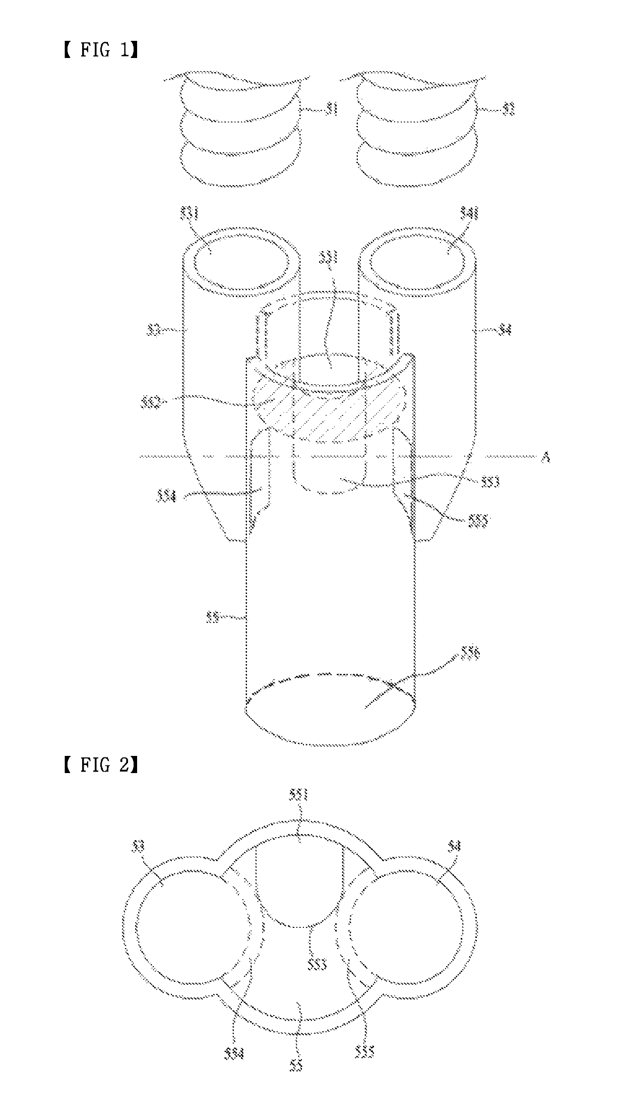
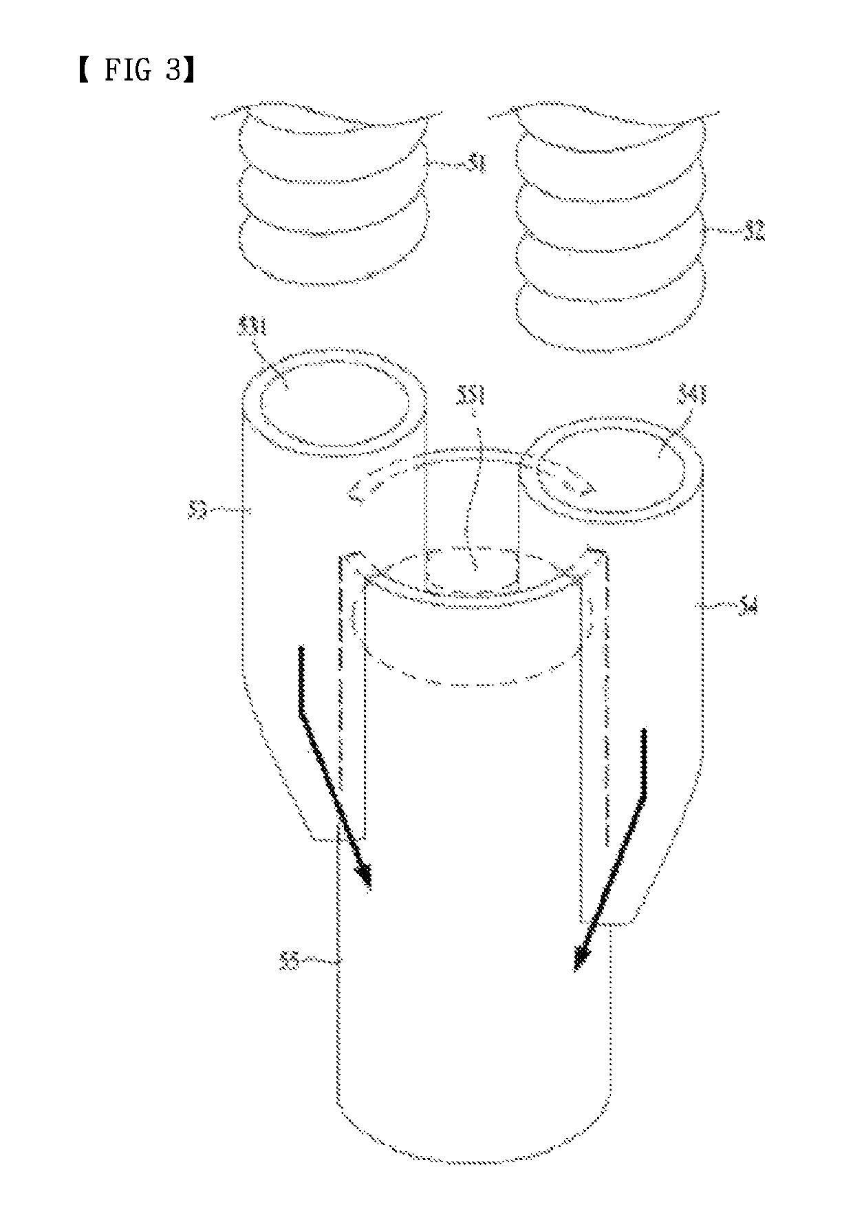
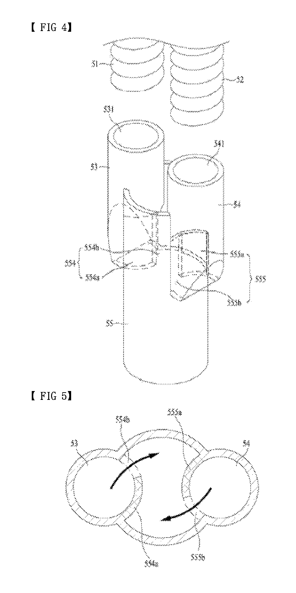
[0031]As shown in FIG. 1, a drainage apparatus in accordance with a first embodiment may include a first inlet pipe 53 for sucking fluid; a second inlet pipe 54 for sucking fluid via another path; and an outlet pipe 55 in which the fluid inflowing to the first inlet pipe 53 meets the fluid inflowing to the second inlet pipe 54. The fluid sucked into the outlet pipe 55 is drained outside along the outlet pipe 55.

[0032]The first inlet pipe 53, the second inlet...


PUM


Abstract

There is disclosed a drainage apparatus capable of allowing the fluid flowing via diverse paths to flow via one path, the drainage apparatus comprising a first inlet pipe fluid flows in, a second inlet pipe fluid flows in, an outlet pipe in communication with the first inlet pipe and the second inlet pipe, a first outlet hole in contact with the first inlet pipe and the outlet pipe and a second outlet hole in contact with the second inlet pipe and the outlet pipe, wherein the first outlet hole and the second outlet hole are provided not to face each other directly.

Description

CROSS-REFERENCE TO RELATED APPLICATIONS[0001]This application claims priority to Korean Patent Application No. 10-2015-0136776 filed on Sep. 25, 2015 in Korea, the entire contents of which is hereby incorporated by reference in its entirety.BACKGROUND OF THE DISCLOSURE[0002]Field of the Disclosure[0003]Embodiments of the present disclosure relate to drainage apparatus for uniting diverse water flow paths.[0004]Background of the Disclosure[0005]A drainage apparatus means the mechanism for draining fluid such as used-water outside a specific device. Such a drainage apparatus is necessarily provided in a laundry treatment apparatus or a dishwasher. The laundry treatment apparatus released recently includes two or more laundry treating apparatuses which are united as one apparatus. One of the apparatuses serves as a washer and the other one serves as a dryer. The laundry treatment apparatus exemplified above is likely to have the wash water contaminated during the washing process and th...

Claims


Application Information

Patent Timeline
Patent Type & Authority Patents(United States)
IPC IPC(8): D06F39/08D06F29/00F16L41/02E03C1/122D06F31/00
CPCE03C1/122D06F29/00F16L41/023D06F39/083D06F31/00
Inventor SANG, MINKYUJANG, HOSANGLEE, JIHONG
Owner LG ELECTRONICS INC
Why Eureka
Try Eureka