Cradle clamp bracket assembly
a clamping bracket and cradle technology, applied in the direction of cranks, eccentrics, mechanical devices, etc., can solve the problems of time-consuming and difficult installation of conventional cable cleats
- Summary
- Abstract
- Description
- Claims
- Application Information
AI Technical Summary
Benefits of technology
Problems solved by technology
Method used
Image
Examples
first embodiment
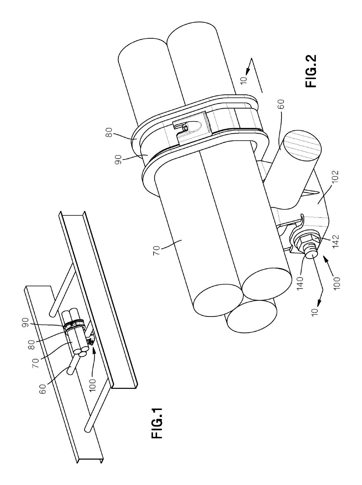
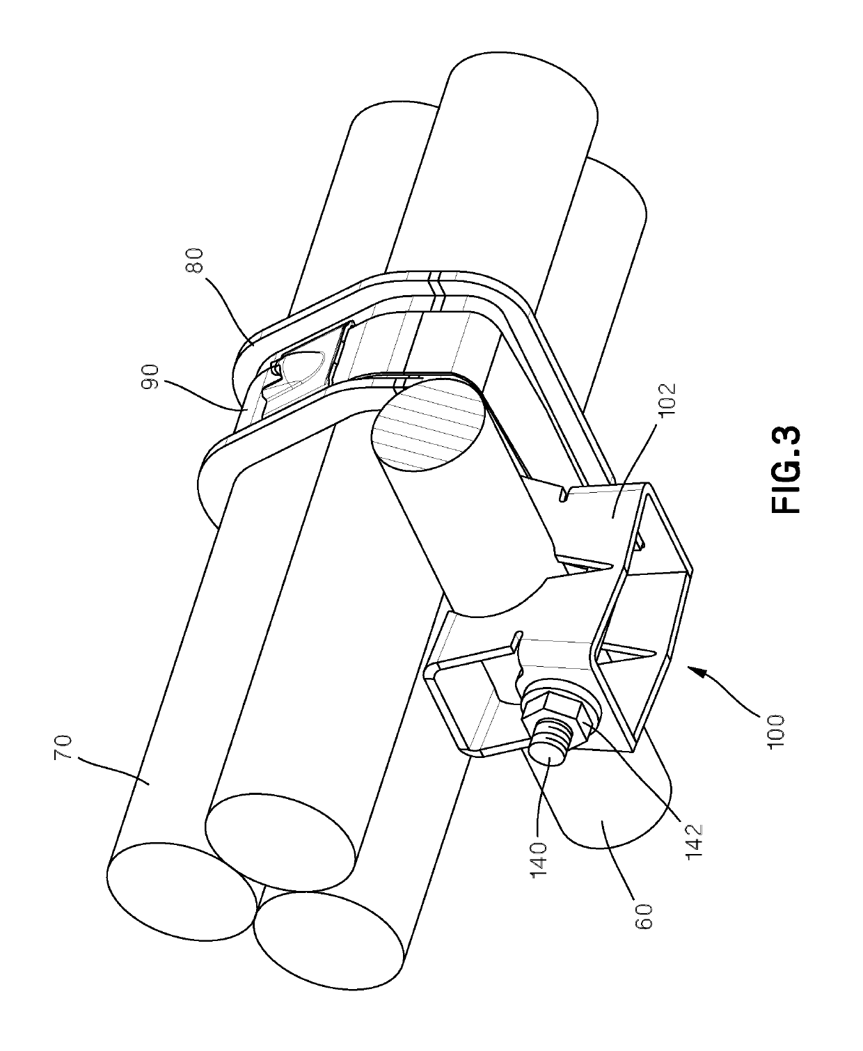
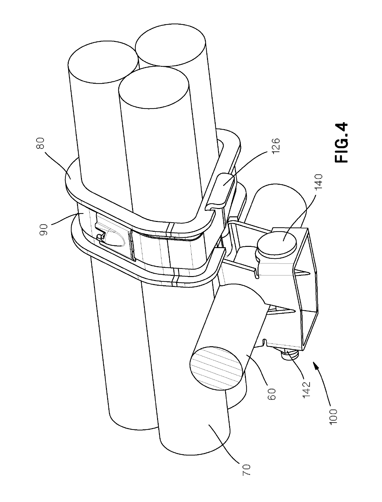
[0093]FIGS. 1-10 illustrate a cradle clamp bracket assembly 100. As illustrated in FIGS. 5 and 6, the cradle clamp bracket assembly 100 includes a one piece metal bracket 102, a carriage bolt 140 and a hex nut 142. The bracket 102 includes a top 104, a bottom 106, a first side 108, a second side 110, a first end 112 and a second end 114. The top 104 of the bracket 102 defines an opening 120 for receiving various sized ladder rungs. The top 104 of the bracket 102 also defines contact points 122 which engage the ladder rung 60 when the cradle clamp bracket assembly 100 is secured. The top 104 of the bracket 102 includes a gusset 124 and a downwardly extending flange 126. The gusset 124 increases the strength of the bracket 102. Each side 108, 110 of the bracket includes an opening 128 for the ladder rung 60 and a V-shaped notch 130. The V-shaped notches 130 enable the bracket 102 to engage the ladder rung 60 when the nut 142 is tightened. A first end 112 of the bracket 102 includes a ...
second embodiment
[0095]FIGS. 11-16 illustrate a cradle clamp bracket assembly 200. As illustrated in FIG. 13, the cradle clamp bracket assembly 200 includes a retainer bracket 202, a metal bracket 222, a carriage bolt 246 and a nut 248. The retainer bracket 202 includes a top 204 with a contact point 206, a bottom 208, a first side 210, a second side 212 and an end 214. The end 214 includes a circular opening 216 for receiving the carriage bolt 246 when the bracket is assembled. The first side 210 and the second side 212 include edges 218, 220, respectively, that define pivot points.
[0096]The metal bracket 222 includes a top 224, a bottom 226, a first side 228, a second side 230 and end 232. The top 224 includes a contact point 234, a gusset 236 and a downwardly extending flange 238. The gusset 236 increases the strength of the metal bracket 222. The end 232 includes a rectangular opening 240 for receiving the carriage bolt 246 when the retainer bracket 202 and the metal bracket 222 are assembled. T...
third embodiment
[0098]FIGS. 17-24 illustrate a cradle clamp bracket assembly 300. As illustrated in FIG. 19, the cradle clamp bracket assembly 300 includes a J-hook 302, a metal bracket 314 and a nut 336. The J-hook 302 includes a top 304 with a contact point 306, a center 308 with a flat member 310 and a threaded end 312. The metal bracket 314 includes a top 316 with a gusset 318 and a downwardly extending flange 320. The gusset 318 increases the strength of the metal bracket 314. The metal bracket 314 also includes a bottom 322, a first end 324, a second end 326, a first side 328 and a second side 330. The first end 324 includes a notch 332 for receiving the flat portion 310 of the J-hook 302 and the second end 326 includes an opening 334 for receiving the threaded end 312 of the J-hook 302.
[0099]As illustrated in FIGS. 20-24, the cradle clamp bracket assembly 300 is secured to the ladder rack similar to the installation of the cradle clamp bracket assembly 200 described above. The cradle clamp b...
PUM
 Abstract
Description
Claims
Application Information
 - R&D
- Intellectual Property
- Life Sciences
- Materials
- Tech Scout
- Unparalleled Data Quality
- Higher Quality Content
- 60% Fewer Hallucinations
Browse by: Latest US Patents, China's latest patents, Technical Efficacy Thesaurus, Application Domain, Technology Topic, Popular Technical Reports.
© 2025 PatSnap. All rights reserved.Legal|Privacy policy|Modern Slavery Act Transparency Statement|Sitemap|About US| Contact US: help@patsnap.com


