
Ball bearing

a ball bearing and ball bearing technology, applied in the direction of rotary bearings, shafts and bearings, rolling contact bearings, etc., can solve the problems of reducing the service life of grease, and achieve the effect of reducing rotational resistance, prolonging the service life of lubricant, and suppressing the shearing of lubrican

Active Publication Date: 2019-09-24
JTEKT CORP
View PDF6 Cites 0 Cited by
  • Summary
  • Abstract
  • Description
  • Claims
  • Application Information

AI Technical Summary

Benefits of technology

This design reduces rotational resistance and extends the service life of the lubricant by minimizing grease shearing and maintaining a smaller rotational speed difference between the cage and the rings.

Problems solved by technology

Further, shearing reduces the service life of grease.

Method used


Image

  • Ball bearing
  • Ball bearing
  • Ball bearing

Examples


Embodiment Construction

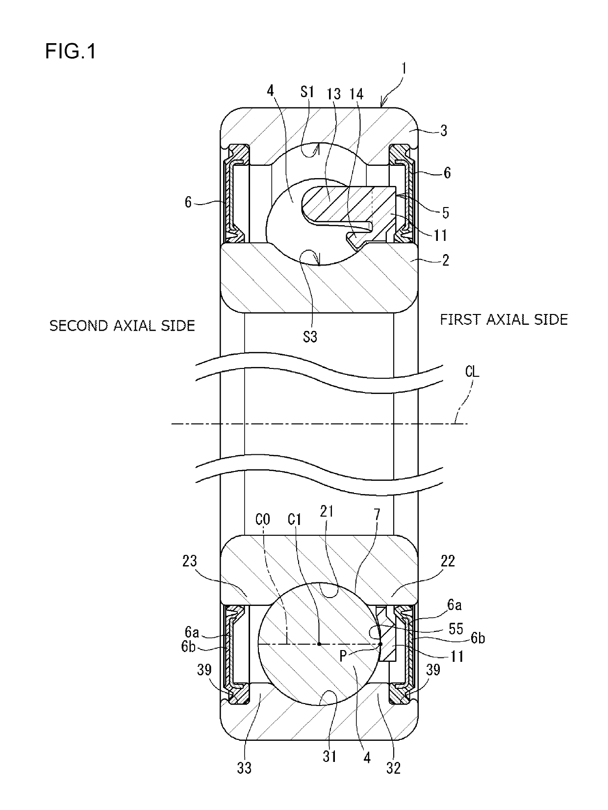
[0018]Hereinafter, example embodiments of the invention will be described with reference to the accompanying drawings. FIG. 1 is a sectional view of a ball bearing according to an embodiment of the present invention. A ball bearing 1 includes an inner ring 2, an outer ring 3, a plurality of balls 4, and an annular cage 5. The outer ring 3 is disposed radially outward of the inner ring 2. The balls 4 are interposed between the inner ring 2 and the outer ring 3. The annular cage 5 holds the balls 4. In the ball bearing 1, grease is provided as lubricant in an annular space formed between the inner ring 2 and the outer ring 3. In the present embodiment, an axial direction includes a direction parallel to a center line CL of the ball bearing 1 (hereinafter referred to as “bearing center line CL”), and a radial direction corresponds to a direction perpendicular to the bearing center line CL.

[0019]The ball bearing 1 illustrated in FIG. 1 further includes a sealing device 6 on each end in ...


PUM


Abstract

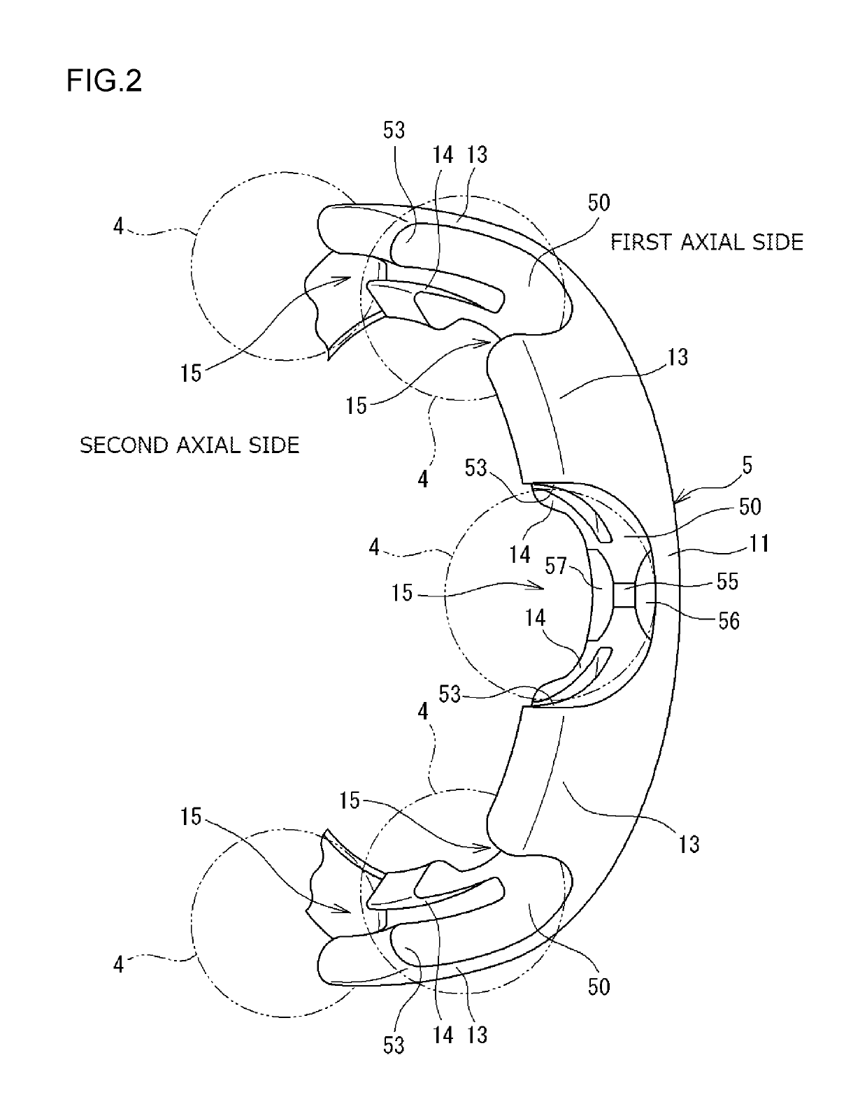
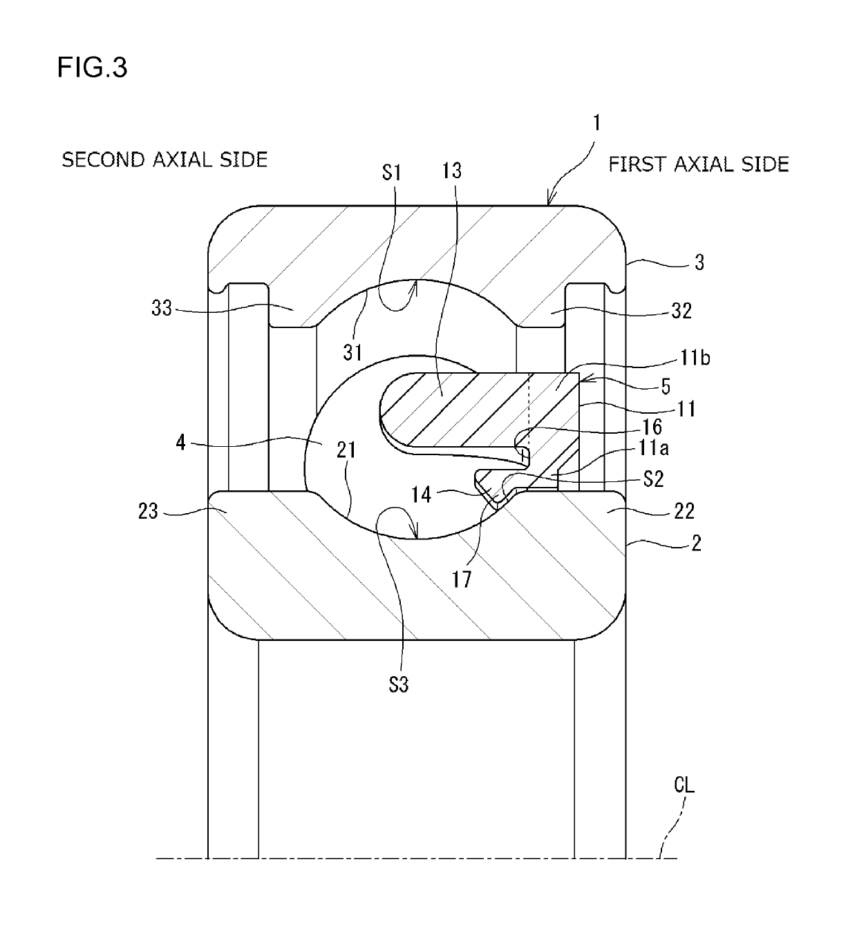
A cage of a ball bearing includes an annular portion located on a first axial side with respect to balls, the first axial side being one side in an axial direction of the ball bearing, and cage bars extending from the annular portion toward a second axial side, the second axial side being the other side in the axial direction of the ball bearing. A space located on a second axial side of the annular portion and defined between any two of the cage bars adjacent to each other in a circumferential direction serves as a pocket that accommodates a corresponding one of the balls. The pocket has a contact surface that is brought into point contact with the ball at an intersection point between a rotational center axis of the ball and a surface of the ball when the cage is displaced toward the second axial side.

Description

INCORPORATION BY REFERENCE[0001]The disclosure of Japanese Patent Application No. 2017-019428 filed on Feb. 6, 2017 including the specification, drawings and abstract, is incorporated herein by reference in its entirety.BACKGROUND OF THE INVENTION1. Field of the Invention[0002]The invention relates to a ball bearing.2. Description of the Related Art[0003]A ball bearing is a low torque bearing (with low rotational resistance), and ball bearings with even lower torque are increasingly required in recent years. The ball bearing includes an inner ring, an outer ring, a plurality of balls and an annular cage. A rotational performance of the ball bearing is secured by grease (lubricant) provided in an annular space formed between the inner ring and the outer ring. The cage functions as a separator that separates the balls disposed between the inner ring and the outer ring. The cage is made of steel or resin. A steel cage has a pair of annular members. The balls are sandwiched between the ...

Claims


Application Information

Patent Timeline
Patent Type & Authority Patents(United States)
IPC IPC(8): F16C33/38F16C19/16F16C19/06F16C33/41F16C19/02
CPCF16C19/02F16C33/3887F16C33/416F16C33/412F16C33/418F16C19/06F16C19/163F16C19/16F16C33/38F16C33/583F16C33/6607
Inventor KAMAMOTO, SHIGEOMURATA, JUNJISHISHIHARA, YUKI
Owner JTEKT CORP
Learn More