Supercharge Your Innovation With Domain-Expert AI Agents!

Controlled translation method of affixing a termination to a tensile member

a technology of tensile members and translation methods, applied in the direction of controlling lamination, other domestic objects, mechanical apparatus, etc., can solve the problems of difficult organization, low efficiency, and difficult handling of synthetic filaments, and achieve the effects of small linear displacement, equal load sharing, and rapid ra

Active Publication Date: 2019-10-08
CAMPBELL RICHARD V +1
View PDF4 Cites 2 Cited by
  • Summary
  • Abstract
  • Description
  • Claims
  • Application Information

AI Technical Summary

Benefits of technology

This method enhances the alignment and load distribution of filaments, resulting in improved breaking strength and repeatability of the termination, with significant advantages over disorganized initial states, and can be monitored through temperature and viscosity changes in the potting compound.

Problems solved by technology

The filaments are very strong in tension, but they are not very rigid.
These facts make such synthetic filaments difficult to handle during the process of adding a termination and difficult to organize.
While the invention could in theory be applied to older cable technologies—such as wire rope—it likely would offer little advantage and the additional time and expense of implementing the invention would not be worthwhile.
Of course, if enough tension is applied the termination will fail.
This view illustrates one of the significant problems of the potting approach.
Once the filaments are placed within the cavity in the anchor, it is very difficult to control their orientation with any specificity.
However, each individual filament tends to bend and slew in a random fashion.
It is not possible to neatly arrange the filaments because there is no way to grip and hold them.
Another known problem is the difference in the filament-to-potting-compound ratio for different regions of the cavity.
Some heat is desirable but too much heat tends to produce short polymer-chain length.
When the liquid potting compound begins to heat up in a given area, its viscosity typically drops and it tends to ooze and fill voids more readily.

Method used


Image

  • Controlled translation method of affixing a termination to a tensile member
  • Controlled translation method of affixing a termination to a tensile member
  • Controlled translation method of affixing a termination to a tensile member

Examples


Embodiment Construction

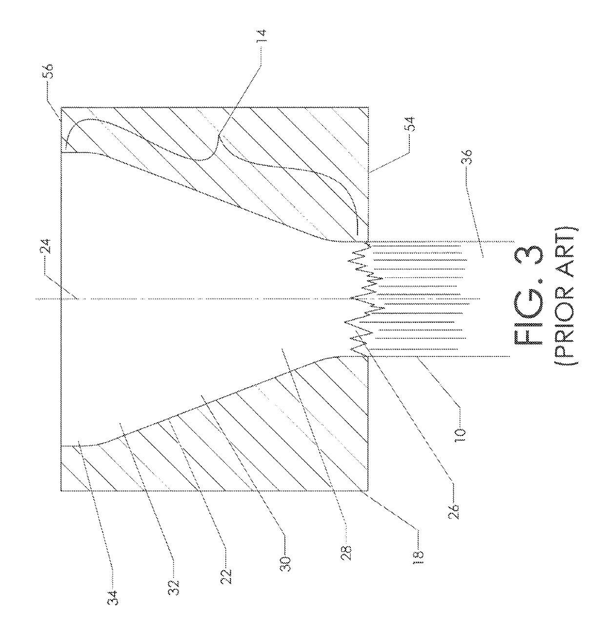
[0082]The present invention takes advantage of the transition properties of the potting compound. Referring hack to FIG. 3, the reader will recall that distal region 32 has a significantly higher ratio of potting compound to filaments than neck region 28. This is true because the cross sectional area of the filaments is the same for both regions, but the cross-sectional area of the expanding cavity is larger in distal region 32. Thus, in distal region 32 the gaps between the filaments are larger and these gaps tend to be filled by the liquid potting compound.

[0083]If a potting compound has an exothermic cross-linking transformation (common for epoxies, polyesters, and many other compounds), then more heat will be generated in distal region 32 as compared to neck region 28. This is true because the distal region has a higher concentration of liquid potting compound and a lower concentration of inert filaments tending to absorb the heat produced. The result is that the temperature wil...


PUM

PropertyMeasurementUnit
tensile strengthaaaaaaaaaa
lengthaaaaaaaaaa
tensionaaaaaaaaaa

Abstract

A method for creating a termination by attaching some kind of fitting to the end of a tensile member such as a cable. The end fitting is provided with an internal cavity. The cavity has a proximal portion that is adjacent the area where the tensile member exits the fitting and a distal portion on its opposite end. A length of the tensile member's filaments is placed within this expanding cavity and infused with liquid potting compound. The method exploits the characteristic of a liquid potting compound as it transitions to a solid. The potting compound in one portion of the cavity is typically transitioned to a solid at a more rapid rate than other portions. Once the potting compound in one portion of the cavity has transitioned sufficiently to hold the filaments at the desired level, tension is placed on the tensile member and a small linear displacement may be imposed on the tensile member. This linear displacement tends to pull the filaments residing in the potting compound into better alignment and improve load sharing.

Description

CROSS-REFERENCES TO RELATED APPLICATIONS[0001]This non-provisional patent application is a continuation of application Ser. No. 14 / 611,350. The prior application listed the same inventors as the present application.STATEMENT REGARDING FEDERALLY SPONSORED RESEARCH OR DEVELOPMENT[0002]Not Applicable.MICROFICHE APPENDIX[0003]Not ApplicableBACKGROUND OF THE INVENTION1. Field of the Invention[0004]This invention relates to the field of tensile strength members. More specifically, the invention comprises a method for affixing a termination to an end of a tensile strength member such as a cable.2. Description of the Related Art[0005]Tensile strength members must generally be connected to other components in order to be useful. A flexible cable provides a good example. The cable must generally include some type of end-fitting so that it can be transmit a load. For example, a cable used in a hoist generally includes a lifting hook on its free end. This lifting hook may be rigged to a load. T...

Claims


Application Information

Patent Timeline
Patent Type & Authority Patents(United States)
IPC IPC(8): B32B41/00F16G11/04F16G11/05B29C65/78B29C65/72B29C65/56B29C65/54B29C65/48B29C65/00B29C65/14B29L31/00
CPCF16G11/042B29C66/91221B29C65/7841B29C66/97B29C66/1286B29C65/72B29C65/561B29C66/95B29C66/344B29C66/69B29C65/48B29C65/54B29C66/742B29C66/112B29C66/12821B29C66/5344F16G11/05B29C66/9121B29C65/546B29C65/4845B29C65/1406B29C65/4815B29C65/485B29C65/542B29C65/4835B29L2031/707
Inventor CAMPBELL, RICHARD V.GLADWIN, DAVID M.
Owner CAMPBELL RICHARD V
Features
  • R&D
  • Intellectual Property
  • Life Sciences
  • Materials
  • Tech Scout
  • Unparalleled Data Quality
  • Higher Quality Content
  • 60% Fewer Hallucinations
Learn More