Blender jar lid with tortuous airflow path

a technology of airflow path and blender jar lid, which is applied in the field of blending jar lids, can solve the problems of separating the lid and creating a mess

Active Publication Date: 2019-10-15
HAMILTON BEACH BRANDS
View PDF28 Cites 1 Cited by
  • Summary
  • Abstract
  • Description
  • Claims
  • Application Information

AI Technical Summary

Problems solved by technology

This is not an issue for one-piece lids that are secured to the jar, but it can cause the cap to separate from the lid.
Foodstuff / liquids may be undesirably expelled from the jar through the air channels during the blending operation, thereby creating a mess.

Method used


Image

  • Blender jar lid with tortuous airflow path
  • Blender jar lid with tortuous airflow path
  • Blender jar lid with tortuous airflow path

Examples


Embodiment Construction

[0025]Certain terminology is used in the following description for convenience only and is not limiting. The words “lower,”“bottom,”“upper,” and “top” designate directions in the drawings to which reference is made. The words“inwardly,”“outwardly,”“upwardly” and “downwardly” refer to directions toward and away from, respectively, the geometric center of the device, and designated parts thereof, in accordance with the present disclosure. Unless specifically set forth herein, the terms “a,”“an” and “the” are not limited to one element, but instead should be read as meaning “at least one.” The terminology includes the words noted above, derivatives thereof and words of similar import.

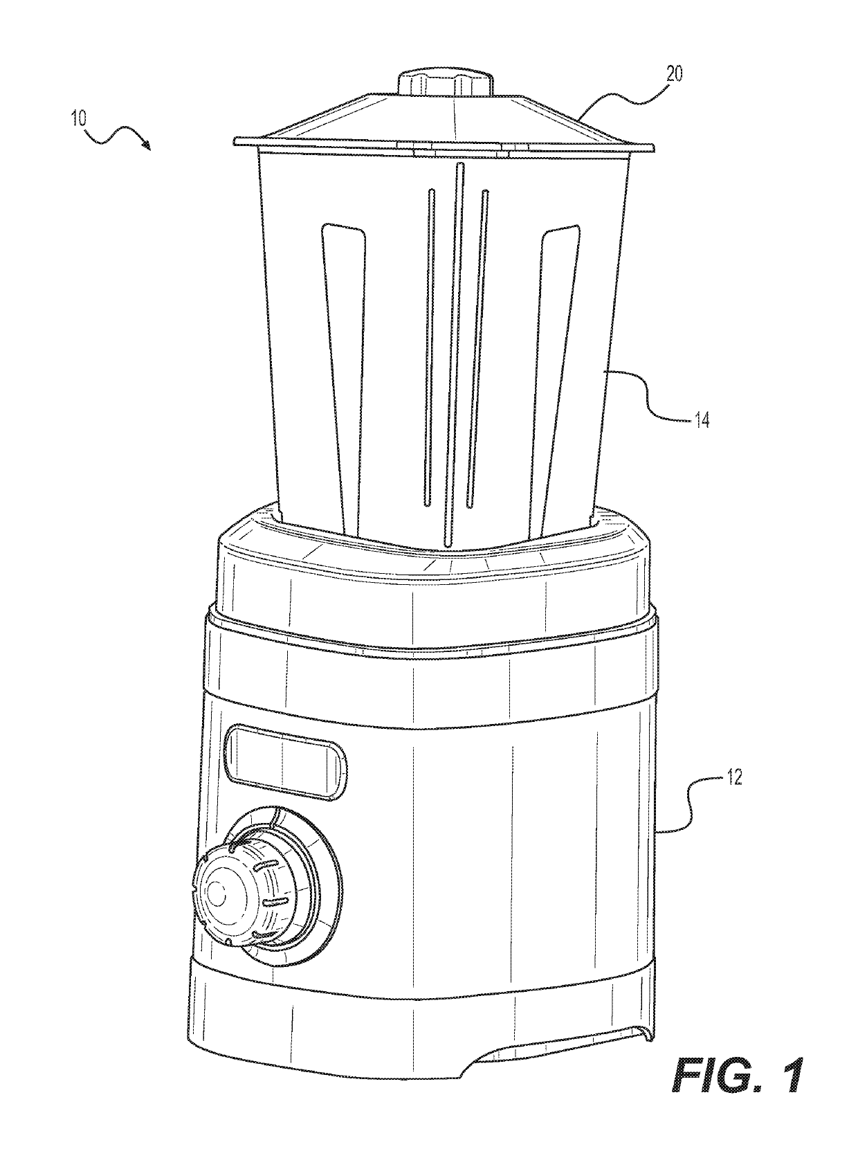
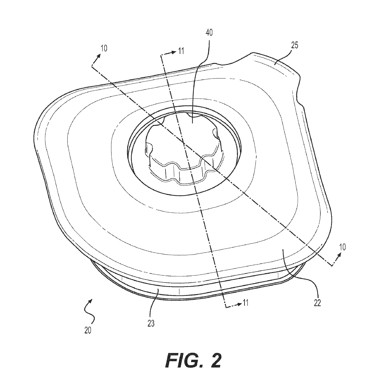
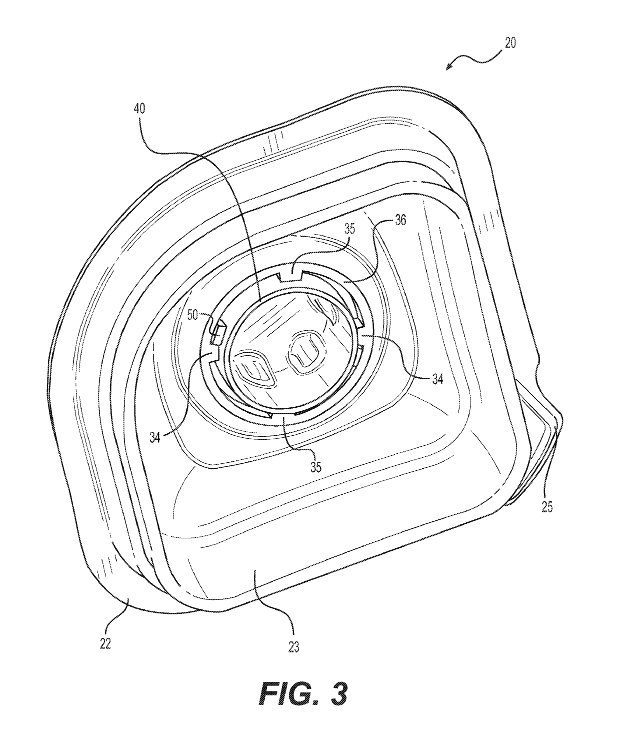
[0026]Referring to the drawings in detail, wherein like numerals indicate like elements throughout, FIGS. 1-11 illustrate a blender or other similar mixing device in accordance with a preferred embodiment of the present disclosure. The blender 10 of embodiments of the present disclosure comprises a base 12...


PUM


Abstract

A blender for blending foodstuff comprises a base enclosing a motor, a jar for containing foodstuff that is removably mountable to the base, and a lid removably mountable to the jar to selectively close off the top end. The lid comprises a main body having an opening defined therein, and a cap removably mountable to the main body to selectively close off the opening. When the cap is mounted to the main body and the lid is mounted to the jar, a tortuous airflow path is provided between the main body and cap to allow airflow into or out of the jar.

Description

BACKGROUND OF THE DISCLOSURE[0001]The present disclosure relates generally to small appliances, and more particularly to blenders for blending foodstuff.[0002]Blenders are a common household appliance and are capable of mixing liquids and chopping dry foods. Blenders are also useful for liquefying fruits and vegetables and for blending solids with liquids. A typical blender includes a blender jar that sits on top of a blender base. The blender jar has an open top end that is selectively closed off with a lid. Foodstuff is placed into the container, the lid is mounted on the blender jar, and the blender jar is engaged with the blender base. The foodstuff is blended within the volume defined by the blender jar, and the blender jar is removed from the blender base to dispense or pour the blended foodstuff.[0003]Most lids are one-piece units, but some have a removable center portion called a cap. The cap is selectively removable to reveal a secondary opening through the lid so that addi...

Claims


Application Information

Patent Timeline
Patent Type & Authority Patents(United States)
IPC IPC(8): A47J43/07A47J43/046B01F15/00A47J31/44A47J36/06
CPCA47J43/046A47J43/0716A47J31/4407B01F35/45B01F2101/1805
Inventor LEPPERT, KEVIN LDICKERSON, JUSTIN KYLEELLIOTT, JOSEPH R
Owner HAMILTON BEACH BRANDS
Why Eureka
Try Eureka