Immediate manual locking arrangement for retractable lanyards and uses therefor

a retractable lanyard and manual locking technology, which is applied in the field of retractable lanyards, can solve the problems of unsafe conditions, undesired positions, and inability to know beforehand how much of the line will become exposed, and achieve the effect of being easy to “lock”

Active Publication Date: 2019-10-15
HINNANT GARRETT LEE
View PDF21 Cites 2 Cited by
  • Summary
  • Abstract
  • Description
  • Claims
  • Application Information

AI Technical Summary

Benefits of technology

[0006]The needs remaining in the prior art are addressed by the present invention, which relates to a manual mechanism for immediately locking a retractable lanyard and, more particularly, to a locking mechanism that is easily manipulated by the user and locks the assembly immediately with a precise, desired amount of cable exposed. The mechanism is easily “locked” and “unlocked” by the movement of a lever, and can be added to or manufactured within a lanyard to override the existing latching mechanism.

Problems solved by technology

While useful in the prevention of pay-out, this type of retractable lanyard cannot be “immediately locked” at any desired location.
As a result, there is no way to know beforehand how much of the line will become exposed before the locking mechanism engages.
In some cases, too much line becomes exposed before locking occurs and may result in an unsafe condition or an undesired position.
Simply stated, a user of a retractable lanyard cannot gauge exactly how much line will be let out before locking occurs.

Method used


Image

  • Immediate manual locking arrangement for retractable lanyards and uses therefor
  • Immediate manual locking arrangement for retractable lanyards and uses therefor
  • Immediate manual locking arrangement for retractable lanyards and uses therefor

Examples


Embodiment Construction

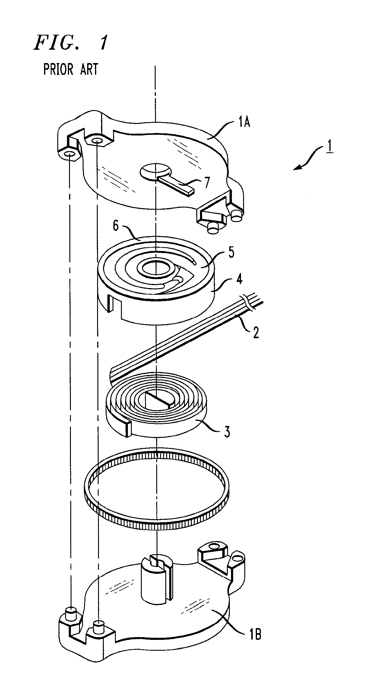
[0024]FIG. 1 illustrates relevant components of a prior art retractable lanyard that are useful to understand so as to fully appreciate the improvement provided by the present invention. Shown in FIG. 1, in exploded view, is a typical housing 1 (including a top housing plate 1A and a lower housing plate 1B) for enclosing a retraction mechanism that controls the movement of a line (or cable) 2. The retraction mechanism allows for a portion of line 2 to be pulled out of housing 1 and then held fixed in place. The same mechanism is activated to disengage the locking arrangement such that the payed-out portion of line 2 is retracted to be stored within the housing. A heavy-duty spring 3 is used to provide the necessary tension on line 2, and line 2 is wound within a spool 4. As shown, spool 4 contains a number of separate sections 5 (referred to as “tracks”) formed in its top surface 6. A reader arm 7, or similar element, engages with tracks 5 in a known manner to control the pay-out of...


PUM


Abstract

A manual mechanism for immediately locking a retractable lanyard is proposed where the locking mechanism is easily manipulated by the user and locks the assembly immediately with a precise, desired amount of cable exposed. The mechanism takes the form of a set of spring-loaded locking pins that engage the tracks on the top of the cable spool. A lever controls the spring and moves the pins between engaging with the spool (the “locked” position) when the spring is compressed, and “unlocked” when the spring is relaxed and the locking pins are retracted. This mechanism can be added to or manufactured within a lanyard to override the existing latching mechanism.

Description

CROSS-REFERENCE TO RELATED APPLICATIONS[0001]This application claims the benefit of U.S. Provisional Application Ser. No. 62 / 369,374, filed Aug. 1, 2016, and herein incorporated by reference.TECHNICAL FIELD[0002]The present invention relates to a retractable lanyard and, more particularly, to a locking arrangement for providing immediate, manual locking of the lanyard at any desired location.BACKGROUND OF THE INVENTION[0003]Retractable lanyards are known in the art and are configured to attach to a person or object, allowing for a range of motion, but preventing a free-fall accident by preventing the complete pay-out of the line. In many designs, a multi-piece reader arm and spool are configured to prevent the pay-out, where the spool is formed to include a number of tracks and as the spool rotates, the reader arm will gradually engage with one of the tracks to prevent further rotation of the spool.[0004]While useful in the prevention of pay-out, this type of retractable lanyard can...

Claims


Application Information

Patent Timeline
Patent Type & Authority Patents(United States)
IPC IPC(8): B65H75/44B65H75/48
CPCA62B35/0093B65H75/4431B65H75/4402B65H75/4442B65H75/486
Inventor HINNANT, GARRETT LEE
Owner HINNANT GARRETT LEE
Why Eureka
Try Eureka