Forced convection steam assembly

a convection oven and steam assembly technology, applied in the field of convection ovens, can solve the problems of large power boilers, large power boilers, and large stand-alone steam systems, and achieve the effects of reducing and increasing the cost of welding

Active Publication Date: 2019-10-22
WHIRLPOOL CORP
View PDF308 Cites 28 Cited by
  • Summary
  • Abstract
  • Description
  • Claims
  • Application Information

AI Technical Summary

Benefits of technology

[0002]One aspect of the present invention is an oven with a housing defining a cooking cavity. The oven has a door coupled to the housing. The oven has a convection fan assembly with a convection fan and at least one heating element to generate heat and to heat the air in the cooking cavity. The oven also has a trough assembly with a trough tray portion located underneath a portion of the convection fan and the convection fan heating element. The trough assembly also includes a trough supply portion shaped to receive fluid and to direct the fluid to the trough tray portion so that the fluid can be heated and turned into steam by the heating element(s) and blown into the cooking cavity by the convection fan.
[0003]Another aspect of the present invention is a convection fan assembly with a steaming device. The convection fan assembly has a convection fan connected to a motor that rotates the convection fan and at least one generally annular heating element coupled near the convection fan. The convection fan assembly also has a trough assembly. The trough assembly has a trough tray located underneath a portion of the convection fan and the generally annular heating element(s). The trough assembly also has a trough supply portion shaped to receive fluid and to direct the fluid to the trough tray portion so that the fluid can be heated by the generally annular heating element(s) and turned into steam, which is blown by the convection fan.

Problems solved by technology

Stand-alone steam systems are very large and costly to integrate into a cooking appliance.
For example, a powered boiler is large, expensive, and requires welding and additional electrical power which may require sharing power with the heating elements and / or the convection fan motor.

Method used


Image

  • Forced convection steam assembly
  • Forced convection steam assembly
  • Forced convection steam assembly

Examples


Embodiment Construction

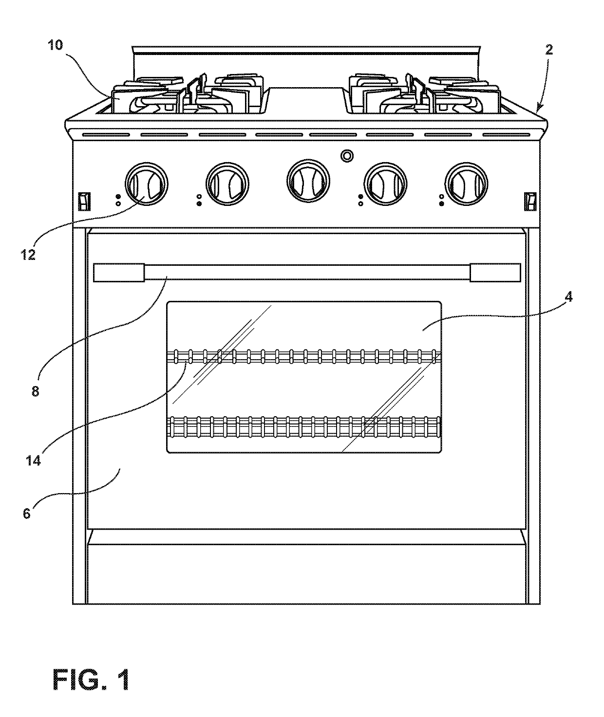
[0013]As referenced in the figures, the same reference numerals may be used herein to refer to the same parameters and components or their similar modifications and alternatives. For purposes of description herein, the terms “upper,”“lower,”“right,”“left,”“rear,”“front,”“vertical,”“horizontal,” and derivatives thereof shall relate to the present disclosure as oriented in FIG. 1. However, it is to be understood that the present disclosure may assume various alternative orientations, except where expressly specified to the contrary. It is also to be understood that the specific devices and processes illustrated in the attached drawings, and described in the following specification are simply exemplary embodiments of the inventive concepts defined in the appended claims. Hence, specific dimensions and other physical characteristics relating to the embodiments disclosed herein are not to be considered as limiting, unless the claims expressly state otherwise. The drawings referenced here...


PUM


Abstract

A convection oven includes a convection fan assembly and a trough assembly that surrounds a portion of the heating element(s) of the convection fan assembly. Fluid in the trough assembly is heated and turned into steam by the heating element(s) and blown into the cooking cavity of the convection oven by the convection fan of the convection fan assembly. The steam in the cooking cavity provides moisture to the items that are being cooked and / or heated in the cooking cavity.

Description

BACKGROUND[0001]Generally, a convection oven includes a convection fan that is near one or more heating elements. The heating element heats air which is blown into the cooking cavity of the oven by the convection fan. While the convection fan is useful to heat and / or cook an item within the cooking cavity, the heated air blown into the cooking cavity can make the item very dry. Stand-alone steam systems are very large and costly to integrate into a cooking appliance. For example, a powered boiler is large, expensive, and requires welding and additional electrical power which may require sharing power with the heating elements and / or the convection fan motor. Thus, it is desirable to have a convection oven that has a smaller, less-expensive approach to provide moisture into the cooking cavity to help keep the item in the cooking cavity moist.SUMMARY OF THE INVENTION[0002]One aspect of the present invention is an oven with a housing defining a cooking cavity. The oven has a door coupl...

Claims


Application Information

Patent Timeline
Patent Type & Authority Patents(United States)
IPC IPC(8): F24C15/00F24C15/32
CPCF24C15/327F24C15/003
Inventor MAYBERRY, TIMOTHY A.
Owner WHIRLPOOL CORP
Why Eureka
Try Eureka